|
Miter Gear Box Continued
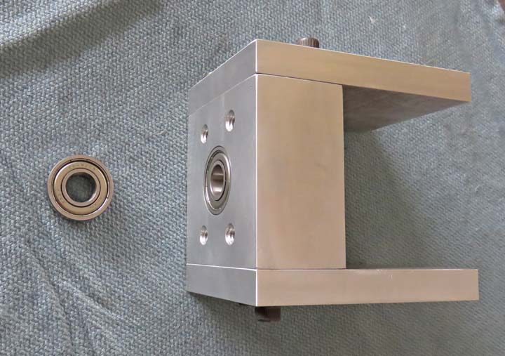
I'm pressing in the bearings here so I can use the center of
them to
indicate from. Yes I could have used the bored hole in the aluminum block without the bearings
in it
but doing it this way eliminates any possible error.
|
|
|
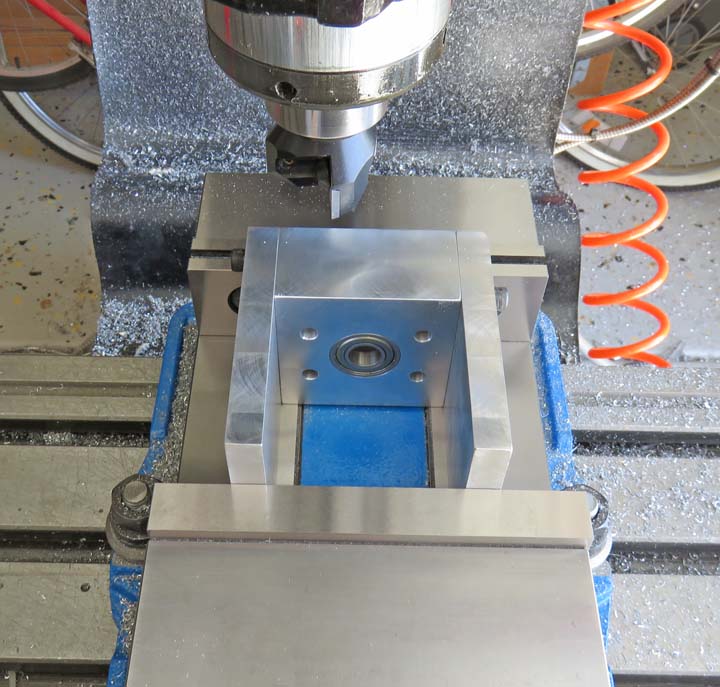
The two side plates line up very well with the bearing
block but I wanted to make sure they were exactly the same size and
location before I put any holes in them. And to do this I'll be taking a
minimum clean-up cut on the front and back surfaces. Also notice the small dots
in the upper corners of the housing. I put one dot each on the left
side (1/2" plate and bearing block) and two dots on the right side. This way I
won't get them mixed up when working with them later.
|
|
|
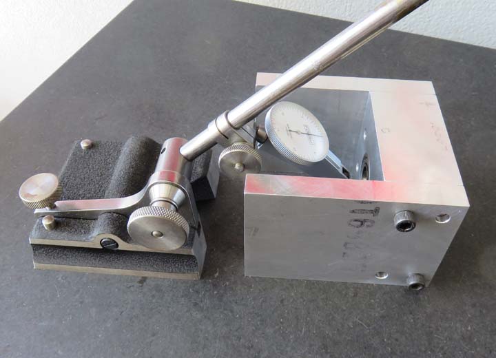
Once I had both sides machined it was time to check if
the bearing was on center or not. To do this I'll be using my granite
surface plate, a surface gage and a .0005 indicator. After checking It
was very close and only off center .001" so I marked the high side and
re-cut it again. I rechecked it after the second cut and the bearing was
exactly on center so now it's time to bore some bearing holes for the
miter gears.
|
|
|
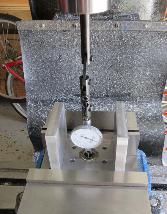
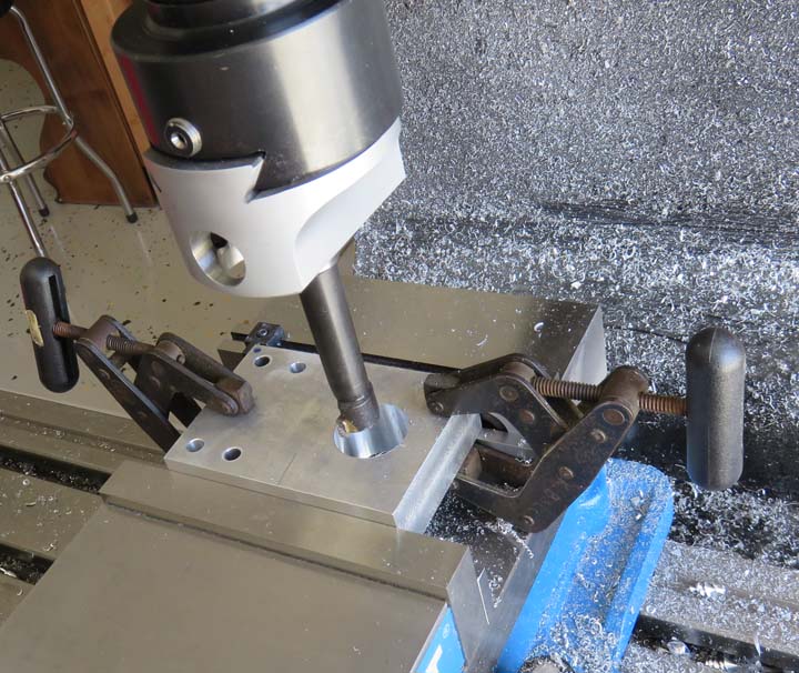
I'm finding the center of the bearing here because the
shaft for the miter gears needs to be at this exact location. Once I
found my center, I zeroed out my digital readout in the Y direction
(front to back). This is critical because the less error here the
better. Now it's time to remove the side plates and bore some holes. If
this is confusing to you, it should make sense in the next few pictures.
|
|
|
After I removed the plates from the bearing block, I
turned them on their sides and clamped them together. This was to make
sure both bearing holes were in the same location. And by clamping on
the same surface that I just indicated from (above picture), the holes
will be in the right spot in my Y direction (front to back). As for the
X dimension (side to side), I had to calculate where they needed to be based on the size of the gears.
|
|
|
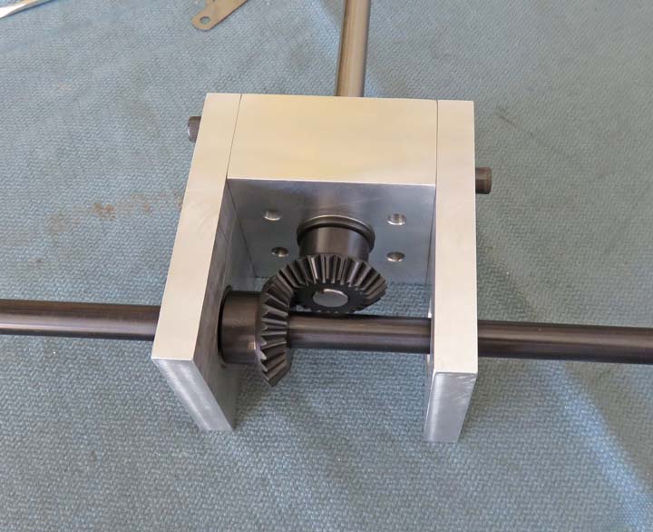
This is what it looks like once I put the bearings in
along with the gears. I left myself an out here by putting a spacer
behind the upper gear which is just a thick washer. This way I can
either make a new one or shim this one till I get the correct backlash.
And I'll do the same thing on the other gear too. Next I'll need to
install some retainer clips on each end of the plain shaft along with
one clip at the front of the shaft with the keyway.
|
|
|
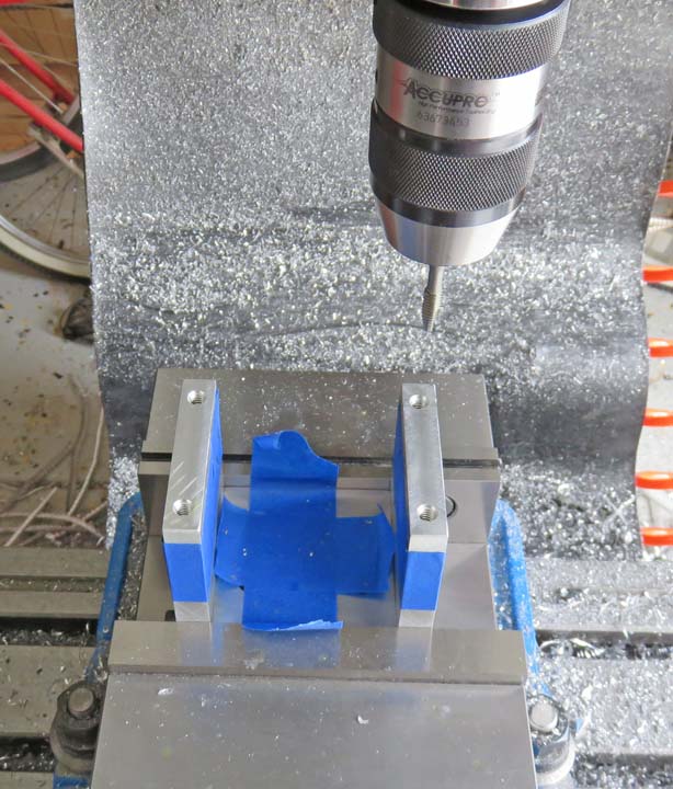
With the miter gears close to working now, it's time to
make a bottom plate for the gear housing. I'm drilling and tapping four
1/4-20 screws to hold it on. Notice I placed tape on all the bearings so
nothing gets into them. Just playing it safe here.
|
|
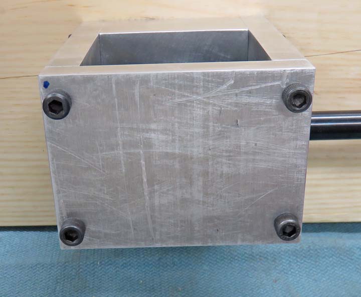
The bottom plate fits great so now it's time to
take it all apart and work on the miter gears.
|
 |
|
1
2
3
4
5
6
7
8
9
10
11
12
13
14
15
16
17
18
19
20
21
22
23 |