|
Component Parts Continued
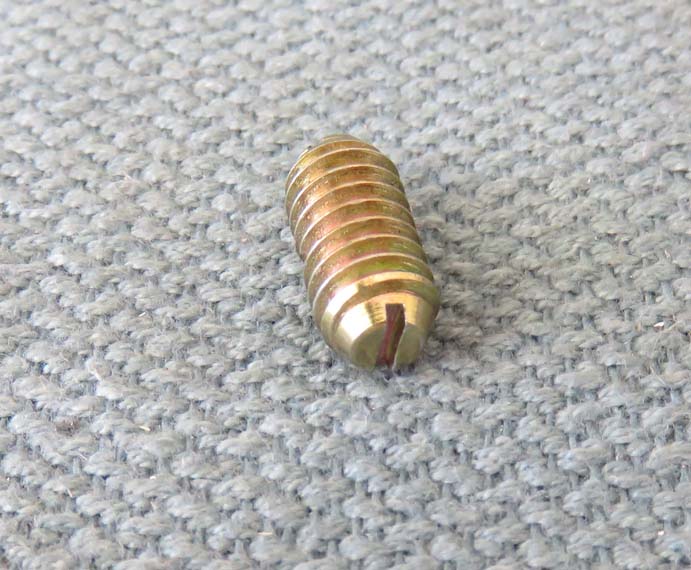
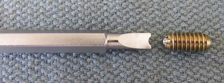
Here is what the screwdriver slot looks like on the
1/4-20 threaded ball plunger with the higher spring rate. While I was
working on the previous one, I forgot to take a picture of it before
I sanded it.
|
|
|
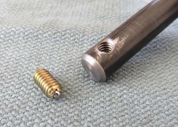
Now that I've narrowed down the one I'll be using, I drilled
and tapped the three shafts for 1/4-20 threads. Now I only bought 'one'
each of the ball plungers but for testing I'll use them both.
The placement of threads in the shaft were based on a
few factors and was calculated earlier. I added up all the components that
I'd be using and came up with what you see below. And once the gear has
been placed on the shaft, the gear will have a small amount of play
between the ball plunger and a permanent stop, which I'll talk more
about later.
|
|
|
With the screwdriver slot now gone I'll need another way
of threading in these ball plungers. If you notice in the picture above
(the area around the ball), there are small slots on both sides of it.
These slots are an alternate method of screwing these units in, but you
need to overcome the spring pressure behind the ball first. To make
matters worse the round ball makes it very hard to find those slots
because your screwdriver blade wants to slip off them very easily.
What I plan on doing is making a custom screwdriver blade so I can use
this slot to thread them in with.
|
|
|
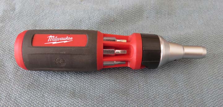
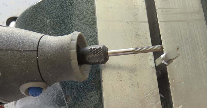
I used my Dremel to put a half-round slot in the
screwdriver blade which worked great and it was quick. I also found out
this blade was very hard so if you're in the market for a Milwaukee
screwdriver set like I'm using, it should last a long time.
|
|
With the slot now in the blade this made it much easier to screw
these ball plungers in now.
|
|
|
I'm using a scrap piece of wood for testing here. I
drilled three clearance holes through the wood, a 9/16" hole for the
shaft and 11/32" for the bolts (1/32" oversize for the bolts).
|
|
|
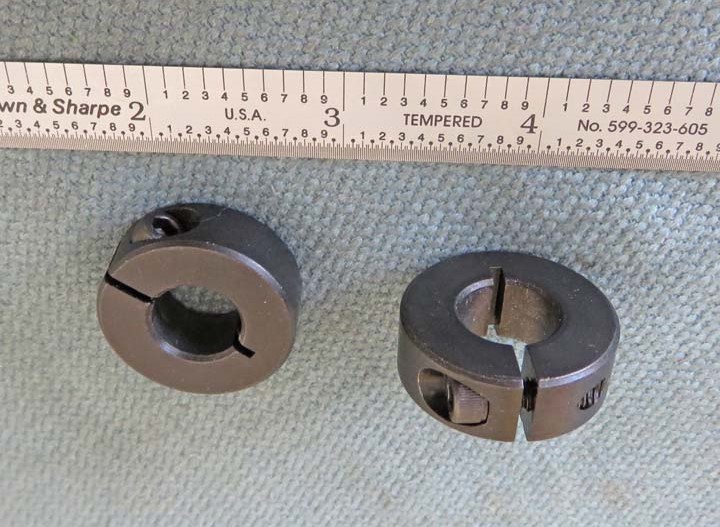
This round piece is called a 'shaft collar' and is
1 1/8" O.D. (outside diameter) X 13/32" thick and has a 1/2" hole
through it.
This collar has a 8-32 socket head cap screw (you need a hex key to
tighten it) and can be placed where ever you want on the shaft. Once it's
tightened it stays in place and works great. I bought three of these for
testing and so far I really like them. This is what I'll be using as my
'stop'.
|
|
|
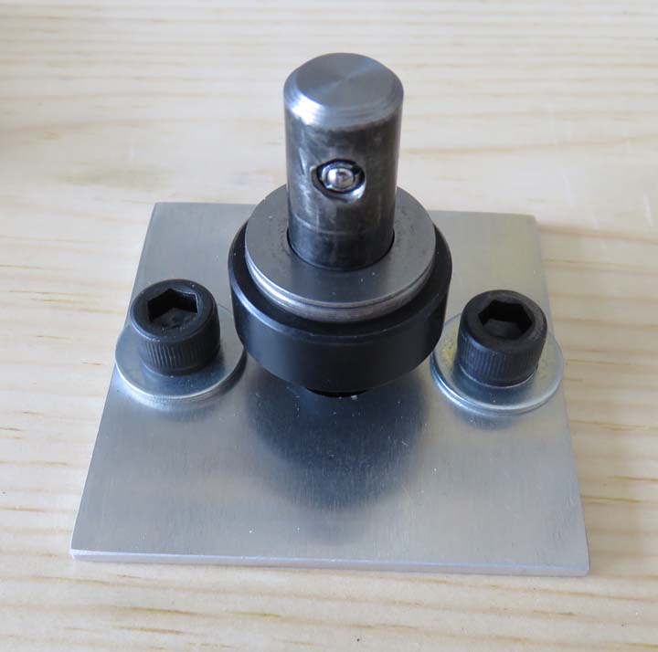
This close-up will be easier to see what I'm working
with. The lighter colored piece on top of the collar is a
'thrust bearing' and again I'm testing here so I'm not sure what I'll
end up using. Once the gear slides onto the shaft, it will
be captured by the ball plunger and won't come off. And this is the main
objective here, not having the gear come back off the shaft because once
they're all spinning, they'll need to stay put. And so far it works
great!
|
|
|
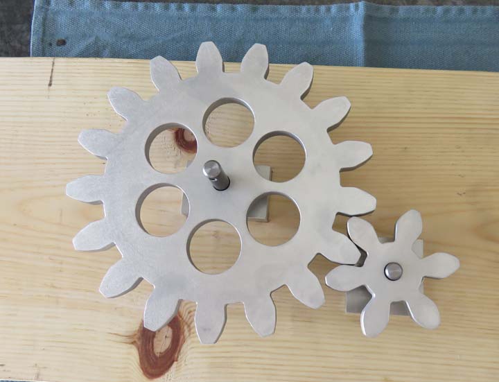
Backlash: One more thing you should also know about gears, it's called 'backlash'.
This is very important because all gears have some kind of backlash which is the slop
(or play) between
each gear tooth. If you have too much backlash the gears will
rattle and wear wrong. If to little backlash, the gears will bind. I'm
lucky here because the gears I'll be working with won't have a 'load' on
them so I can get away with the backlash tolerance being larger than
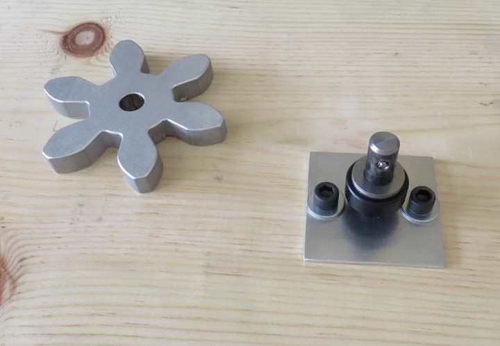
normal. Notice the larger gear is not fastened to the
wood yet. I'm just getting a feel here of how I'm going to get it in the
right location.
|
|
|
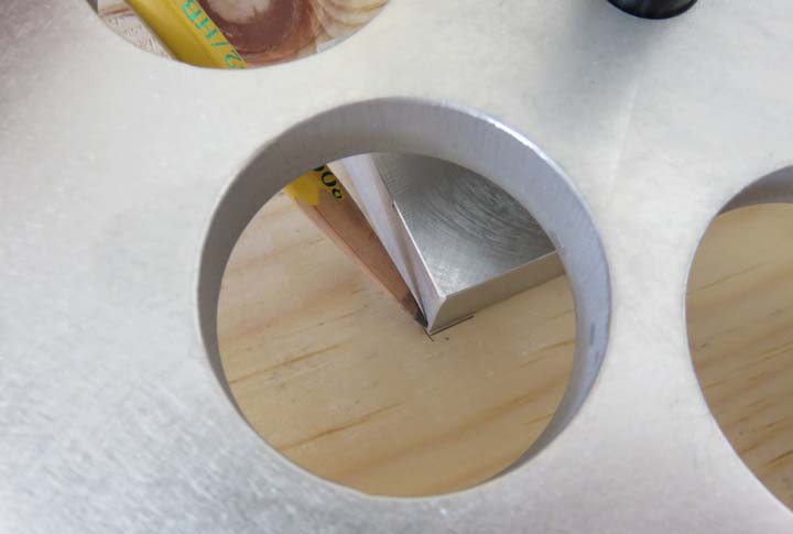
I played with the backlash between these two gears and
after a few minutes I came up with a plan. By placing a shaft collar
under the larger gear (above), this would allow me to align both gears on the
same plane. Once I had the two gears adjusted with the correct backlash,
I used a pencil and drew around two corners of the aluminum block.
|
|
|
1
2
3
4
5
6
7
8
9
10
11
12
13
14
15
16
17
18
19
20
21
22
23 |