|
Component Parts Continued
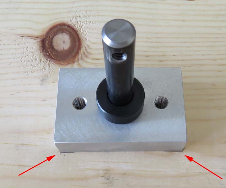
Once I removed the gear from the shaft, I realigned the
block to my pencil marks (arrows), then I transferred the location of
the bolt holes with a pencil placed
through each threaded hole. I then used my trim piece and lined up those two holes
over the pencil marks, which
would also give me the location for the shaft as well. Once they were all
marked I drilled a 9/16 clearance hole for the shaft and two 11/32
holes for the bolts.
This sounds complicated but it's not and it went fast.
This method also worked like I planned because with the three holes
in the wood being much larger than they needed to be, this would allow me to
fine tune
the backlash for the gears.
|
|
| One step forward, two
steps back.
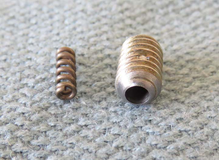
What you see below is a ball plunger that went all
wrong. So....what happened exactly? Remember how I needed to sand the
back of the first ball plunger so it would fit the shaft? While I was
sanding this one, I would stop and measure it to make sure it matched the other
one but I ended up making this one just a little shorter. Once I put pressure
on the ball with my custom screwdriver blade, the spring flew out the back.
What I didn't realize was the wall thickness next to the
spring was paper thin and it broke free. Although when I had finished
sanding it I had no idea how thin this was and it made me re-think this
whole ball plunger idea. I mean what if this happened while the escape
game was in progress, not a good thing. It made me realize something else, if one of these ever needed to be replaced down the
road, it would be very hard to do, even with the custom screwdriver
blade. Time to rethink this ball plunger idea....or is it?
|
|
|
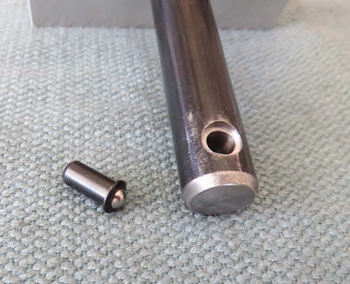
After thinking about my problem and looking a little
harder I found another ball plunger and ordered some. This one doesn't have any threads.
And it's the right length. And no screwdriver slot. How did I miss this
style the first time?
These new ball plungers were similar to the others: they
had a pound rating from two to five, the same stainless steel ball size, but
these were designed to be pressed in. And they should be much easier to
change if need be. Bingo, we have a winner!!
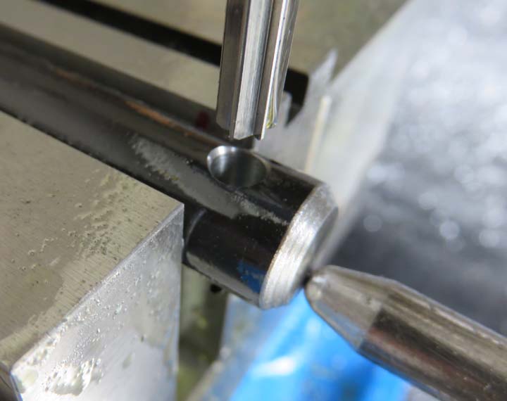
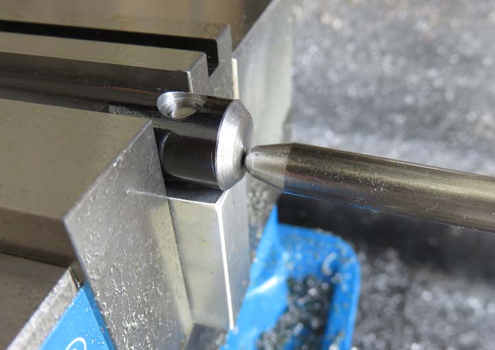
What you see below is the opposite end of the threaded
test shaft but this time I drilled and reamed the hole. I also had to
counterbore for the head which was not hard at all. After experimenting
with it I was sold and decided to use this style of ball plunger. Hot
damn we're back in business!!
|
|
|
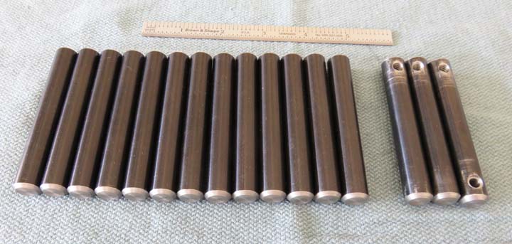
I quickly ordered more material and cut it up, turned
them to length, chamfered them, including the opposite end of the three test
shafts. I also made two extras just in case I needed them.
|
|
|
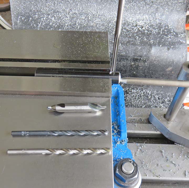
With a new way of holding the gears on now, it's time to
move forward. What I'm doing is center drilling, drilling with two sizes
of drills and then reaming. As you can see I'm using a 'mill stop' at the end
of the shaft so all the holes are in the same location.
|
|
|
These new ball plungers have a .190" body diameter and
I'm using a .191" diameter reamer. If you do the math this 'won't be a
press fit', which is my fault. In this case it will be a slip fit, which
I'll explain: while I was reading about
these new ball plungers on McMaster Carr's website, they gave the size and
tolerance of .190 diameter, plus .002, minus .000. With this
information, I should have ordered the ball plungers first, measured them and 'then' ordered the correct size reamer. I tossed the
dice here and shot for the middle of the tolerance and bought a .191"
reamer. Well that's what I get for guessing so this one's on me.
However, I have a solution that should work out just fine that I'll talk
about in a minute. Notice the chamfer on the reamed hole, this was done
with the center drill. By going deeper than you normally would, I ended up
with a chamfered hole when I'm done reaming (no need to deburr now). This side will be the
bottom when I'm done.
|
|
|
A keen eye may have noticed I didn't do any counterbores
while I was drilling and reaming. Normally you would do this counterbore
operation at the same time because once you take a round part out of the
vise, it won't go back in the exact same place. But I thought of this before I
started drilling and reaming and made a fixture for the counterbore operation.
|
|
|
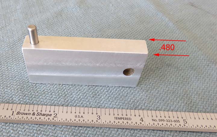
What you see is a small aluminum fixture that I made
from some scrap (hence the hole at one end). The reamed hole in the
shaft is .191" and by using a .1875" pin (3/16 dowel pin), there will
only be a few thousandths difference between the hole and pin. That
difference isn't enough to give me a problem and worked out great. I
also made the thickness of my fixture at .480". This is under the shaft
diameter of .500" so the vise will clamp on the part and not the
fixture.
|
|
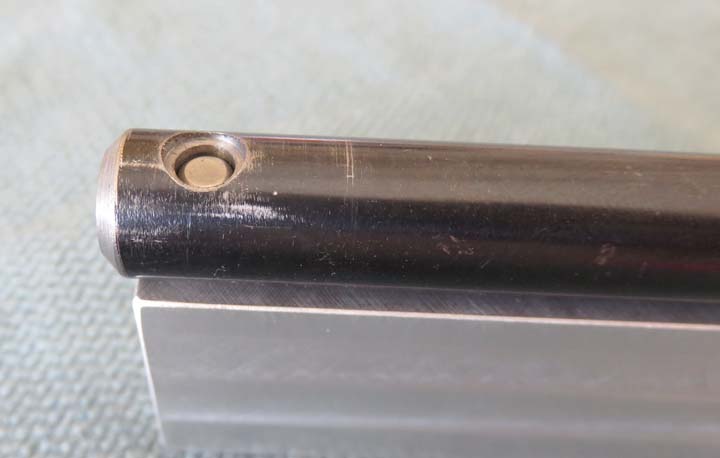
Here is the finished counterbore which came out nice. Sometimes making
a jig or fixture is well worth the time, like in this case.
|
|
|
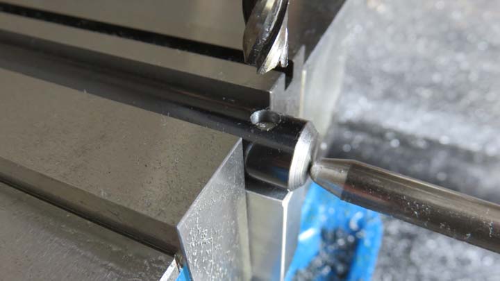
Here you can see how the fixture works. By placing the
pin just below the depth of the counterbore, I can then machine the part
without the cutter hitting the pin and still locate my part. The diameter of the counterbore is
.255" X .060 deep and I used an endmill for this. By hanging the shaft over the
end of the fixture, I located the part accurately against my mill stop.
This operation went pretty quick.
|
|
|
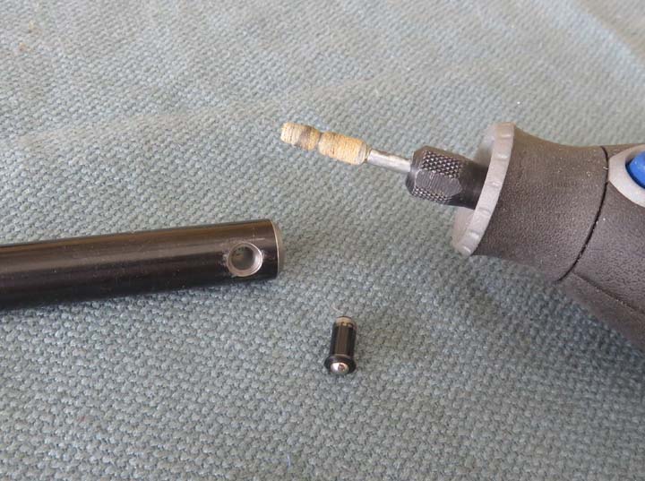
Now that I have all the holes and counterbores finished, it's time to deburr them. I used my Dremel with a
mounted wheel made from cotton
impregnated with grit. This type of wheel works great but it wears
away quickly.
|
 |
|
1
2
3
4
5
6
7
8
9
10
11
12
13
14
15
16
17
18
19
20
21
22
23 |