Component Parts
I'm going to
need a lot of different parts to make all those gears work together so
while they're out getting plated, this will give me some time to work on
other things. Most of the parts I'll be making will be out of aluminum,
mostly for weight reasons because once everything is together it's going
to be very heavy.
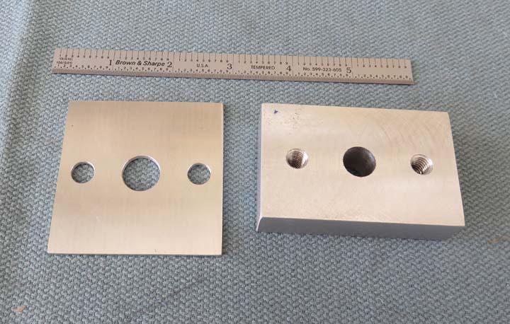
What you see below is a block to hold a shaft (right)
and a thin trim piece. The block measures 2 3/4" X 1 3/4" X 3/4". I drilled
and tapped two 5/16-18 threaded holes to hold it to the plywood and plan
on using .500 (1/2) steel shaft material that will press-fit into this
block. However I don't have the shaft material yet so I drilled the holes
undersize at 7/16" for now. Once I have the shaft
material I can measure it and machine my holes accordingly.
The trim piece that you see will be used on the front
side and will do two things: first it will clean up the area where the shaft
comes through the plywood and second, it will distribute the load of the
bolts to hold the blocks in place. This trim piece is 2
1/2" square X .090" thick and the center hole is 9/16" diameter.
|
|
|
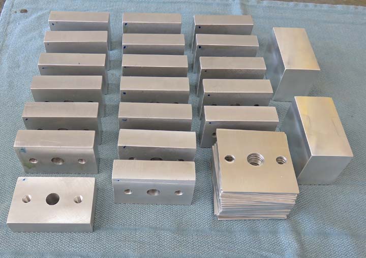
Here are all the blocks and trim pieces. I made a couple
extra just in case something goes wrong. The two blocks on
the right are going to have bearings in them which I'll talk about
soon.
|
|
|
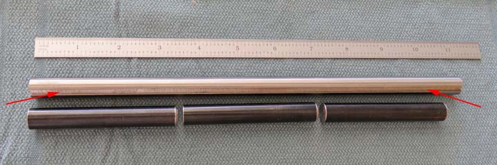
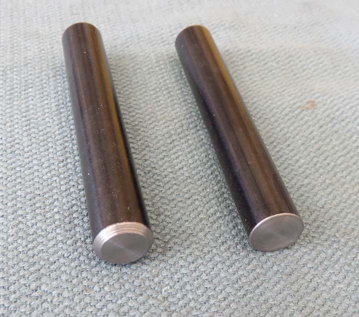
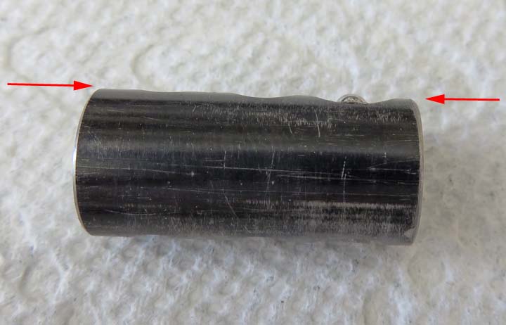
A few days later I bought some shaft material and there are two types:
the
top one has a keyway that runs the entire length (arrows). The
bottom one has no keyway and is easy to tell the difference because it's
black oxide coated. By the way, this coating has a mild rust
preventative and is easy to work with.
The shaft with the keyway has a diameter of .499" and
the other shaft (black) measures in a .4995". I bought one foot of each to do
testing with and if they work then I'll by more later. I also did some
research on different shaft material and a few different companies that
sell them. Amazon has just about everything so this seemed like a
logical place to start. But I quickly found out they didn't have a very
good explanation about some of their products. Don't get me wrong they
have shaft material along with a bunch of other related items, however I
needed more information about each product so I looked elsewhere.
The next place I went to was
McMaster Carr and they
had just what I was looking for. As a matter of fact, I bought just
about everything I needed for this project from McMaster Carr (except
all the pieces that I'll be making). This company has a fantastic
website and is very easy to navigate and search. Once you find your
product they have all kinds of information about it along with many
different types of CAD drawings in case you need those as well. With the
shaft material picked out I was now ready to start testing.
|
|
|
The first thing I did was cut off a one inch piece from each
bar, which was done with my hacksaw on my work bench. Once I started sawing I
knew I had some decent material because it took awhile. Next I took a
clean-up cut off each end and then took them to my work to check the
hardness.
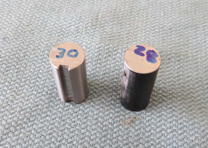
Hardness: The numbers on each piece represents the hardness on the
Rockwell C scale. And if you're not familiar with this scale, it's the
industry standard for checking hardness of steels. In case you were
wondering, softer metals like aluminum are checked on a different scale.
Both of these shafts are the perfect hardness as I can
still drill and tap or machine them without any problems but should be
hard enough to have good wear properties. This information was on
McMaster's website but I just wanted to make sure it matched up. And
Amazon's website neglected to have any of this info which is why I looked
elsewhere.
|
|
|
After drawing some sketches and doing some calculating,
I came up with a length which will be 3.350" long. Note that I chamfered one
end and the other is just deburred. The chamfered end is to aid the gear
being placed onto the shaft. Now this got me
thinking, how am I going to keep each gear from coming back off once
they are in motion? To make sure they don't move too far inward I can
make some kind of a bushing or spacer but how about the other?
|
|
|
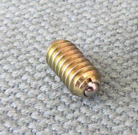
This is what I came up with to keep the gears from
coming back off, a Ball Plunger. Ball plungers have a spring inside the
body that presses against a ball at the end. In my case the ball is made from
stainless steel but they have other materials as well. I bought four different thread sizes
and each one has a different spring rate. The smaller the thread size the lighter
the spring rate. This makes sense because they can only package so much
spring in each size ball plunger.
The sizes I bought are: 6-40, 8-32, 10-30 and 1/4-20.
Those numbers are the thread sizes and start out small and get larger.
The plan is to test each one to determine which one works best.
|
|
|
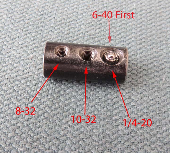
Here is my one inch test piece of plane shaft again and
as you can see it has three different size threads in it. I tried the
6-40 ball plunger first and there just wasn't enough spring pressure.
Side note: there was only one choice for this smaller one, .5 to 1 pound spring rate.
Spring Facts: The reason there are two pound
ratings is because the
farther the ball is depressed, the more spring pressure it exerts. This
is true with any spring.
Second try: I tried the 8-32 size which had a spring rate of
.5 to 1.3 lbs. It was better but still not enough, at least not for me
that is.
Third try: I tried the 10-32 size with a spring rate of 2 to 5
lbs. This was much better and might be just what I was looking for.
Last I drilled out the 6-40 thread and tapped it with
1/4-20 threads. I bought two different spring rates with this larger size:
3 to 7 lbs. and 4 to 12 lbs. I was very optimistic with these heavier
spring rates and they didn't disappoint either. However these larger
ones had one drawback, they were longer than the others and stuck out
the other side of the shaft once I had them adjusted.
|
|
|
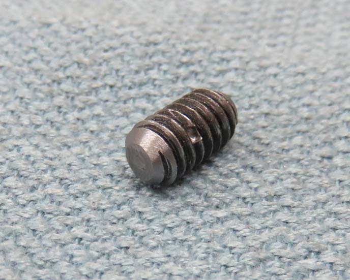
To remedy the length problem, I sanded the back to shorten it which
worked out fine. On the other hand this created another problem. You
see, the backs of all these ball plungers have a standard screwdriver
slot to screw them in with. But once it was sanded the slot was gone.
|
|
|
Here is what the ball plunger looks like with it in the
correct position. The 1/4-20 thread size with the 3 to 7 pound rating
seemed to work well (in the picture below). The heavier spring rate, 4
to 12 lbs. was just a little too much because it was much harder to
slide the gear over it. So how am I going to screw this ball plunger in
without a screwdriver slot?
|
|
|
1
2
3
4
5
6
7
8
9
10
11
12
13
14
15
16
17
18
19
20
21
22
23 |