|
Machining The Gears
The first order of business was to cut off the scale from the outer
surface of the aluminum. Now most metals have a thin 'scale' that might need to be
removed depending on what you're doing (aluminum or steel). For
instance, if you were going to weld on it then the scale isn't something
you'd want because it would contaminate the weld. However, in my
case I'm going to send all these gears to the plating shop to be
anodized. And the type of anodize will be Type III, which is hard
anodize or hard coat anodize. The reason for anodizing is two-fold:
first a lot of people will be handling these gears and being hard anodized
will take the abuse of people bumping them around much better. Second is
because hard anodize will let them 'wear' much longer than just being
raw aluminum. And hard anodize is somewhat slippery which means the
gears will work together much easier. One more thing about hard anodize, this type of plating goes into the
material .001" and builds up on the outside the same amount, .001". In
total that equals .002 of plating buildup (approximately the same
thickness of a human hair). I'll revisit this process later because this
is an important fact.
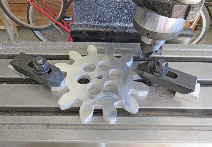
This machining process is an easy one, but the way I have to do it
ends up being a very lengthily one. I'll explain: as you can see I'm holding
the gear with two clamps. Once it's held in place I can machine the
entire top
surface, except the area held by the clamps. Once that's done, I remove both clamps, clean
the part and the milling table surface and then re-clamp on the machined
surface now. At this point I can cut the area that I was previously clamping on so
the entire surface ends up nice and flat. Now I'm only
removing a few thousandths from each surface, in other words a minimum
cleanup. But even if I were taking a large cut in place of this small
cut, I'd still have to do the clamp swap thing. Total time cutting all
the gears was just over eight hours. Like I said, very time consuming.
|
|
|
| With all the gears looking pretty good after being
surfaced, they now had
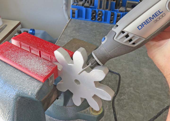
razor sharp edges so they needed to be deburred. I came up with a couple
of ideas for this deburring process but using a Dremel was the best. I
used a carbide burr with a rounded tip at the end to go around each
tooth. The reason for the rounded tip is because it's more
forgiving if you bump into an area by accident. I tried using a burr
with a square end and this is why I switched to one with the rounded
end. This was another easy process but again a very lengthy one. I
would start at the top of the tooth (the small flat area) and I did this
from the front of the gear first. Then I'd move to my right a step or two and lean
over slightly so I could
get to the area that you see below. In this position I could do the long
curved part of the tooth and the bottom area that you see me doing in
the picture.
|
|
 |
|
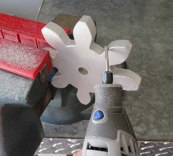
Once I had those two areas done I'd move back to the first position again and do
the adjacent tooth that you see in the picture below. However what you
can't see is 'how' I did this edge break. What I mean is, I didn't just
keep my Dremel at the same angle and run across the surface. What I
ended up doing was starting at a steep angle for my first pass, then
moving to a lesser angle for my second pass, to a lesser angle again for
my third pass, to a much lesser angle for the forth pass and then close
to where I started for my fifth and final pass.
I can only imagine what you must be thinking after reading about this
procedure. The method to my madness is that I wanted the gear to be free
of burrs and if I kept the Dremel in one position while doing this, it
would push a burr on either side of the angled cut when I was done. But
doing it the multi-angled way, there is no burr and it actually has a slight radius
now. Think of the cuts as five small facets very close together that
produces a curve. That's what I ended up with and they all looked great.
The bad news is this process took a very long time. How long you
ask? Keep reading....
|
|
 |
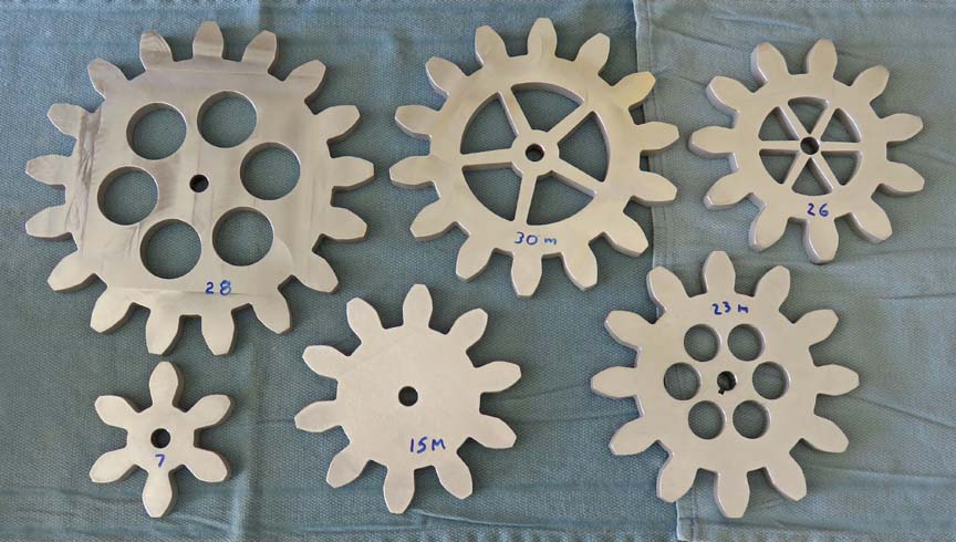
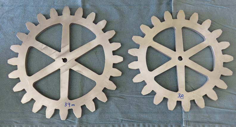
The numbers that you see on each gear is in minutes it took to deburr
each one. Note that the larger one with the holes went quicker than the
smaller one next to it that has triangular windows. The one with the windows are a little
harder to do because those have a little more surface area than the holes.
|
|
|
As the tooth count increases, so does the time it takes
to deburr. The one on the left is the largest gear at 12" pitch
diameter. Total time deburring all of the gears was 10 1/2 hours.
|
|
|
Now that all the gears are easy to handle (no burrs),
it's time to do more machining on them. When I was in the planning
stages, one of the things I decided on was to use .500" diameter (1/2)
shafts for all the gears to spin on. With this number in mind I asked
Scott at R & I Industries what kind of tolerance they could hold with
their water jet machine? The reason I asked him is because I needed
to know if he could put the exact size hole in the gears that I needed.
He told me that he could hold about .010 thousandths of an inch. Well that
wasn't going to work for me so I drew all the gears in my CAD system with the holes undersize,
knowing later I'd open them all up to the size I needed.
In this machining operation I'll be reaming all the
gears to my final size of .503. I'll explain this odd size later. And to
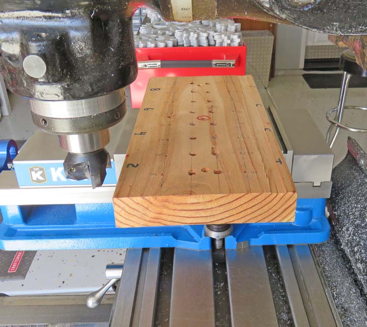
aid me in holding them all in the same place, I'll be making a fixture.
This fixture will be made out of a scrap piece of wood, a 2 X 8 Douglas
fir to be exact. Wood tooling works great for a job like this, and it's
easy and cheap to use. What I'm doing is taking a clean-up cut on the
top and bottom surface to make sure it sits flat and parallel before I
start machining.
In case you were wondering what all those holes were
for, I used this same piece of wood for separating all my
valve train components
while working on my 33 Coupe awhile back.
|
|
 |
I clamped the freshly cut wood tooling down to my mill table and then drilled and
bored two different size holes. You're probably wondering why I have two
sizes? Keep reading.
|
|
 |
|
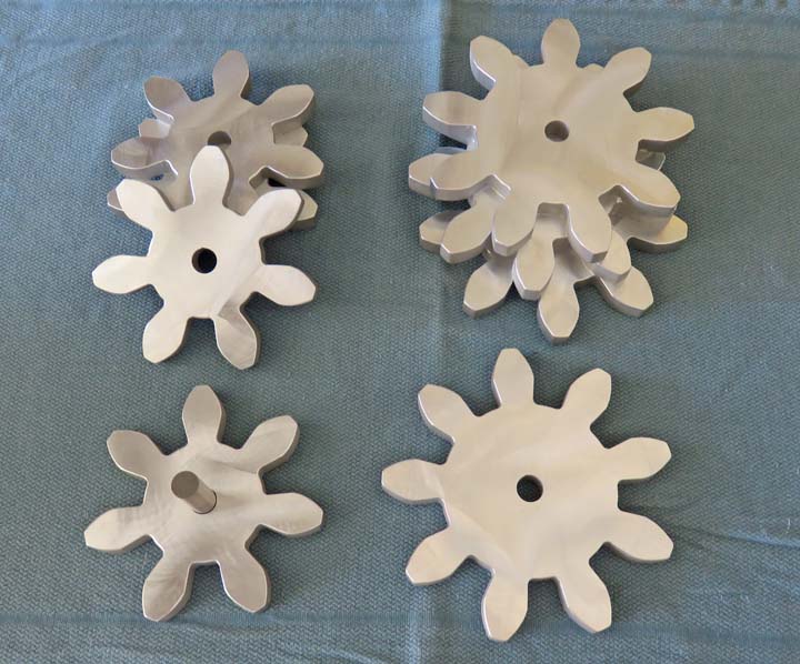
The gears that you see below had to be made over again by R & I Industries and
the reason is because the holes were off center. I noticed this problem
the day Angela and I picked them up because I looked at each and every
gear before we went home. And for some reason only these two
sizes had this off center problem. Scott was very sorry and didn't know
what happened either but he had no problem making them over and then
shipped them to me.
However, the holes in these new gears were different than
all the others so this is why I have two different sizes in my
wood tooling.
|
|
 |
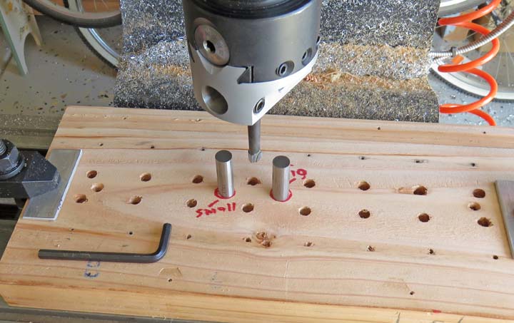
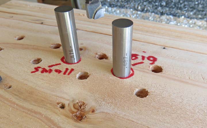
Here you can see the different size pins I'll be using along with my
fancy marking system to let me know which gear goes where. BTW, the
replacement gears have the larger holes.
|
|
 |
|
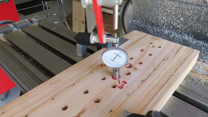
A keen eye will notice that I've turned my wood tooling 90 degrees. What I'm doing is indicating my
gage pin so it will be in
center of the spindle.
|
|
 |
|
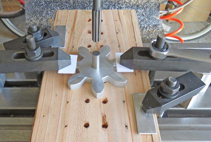
Here you can see one of the gears clamped down and ready to be machined.
Here is how it works: I place the gear on the wood, put the pin through the gear
and into the wood tooling, clamp the gear down, remove the pin and then
ream the hole. This makes it so much easier to center each part and is
well worth the time doing so. Yes I could have floated the reamer
through each hole but I wanted to have each part clamped while reaming.
Why you ask? Sometimes while reaming parts, they tend to climb the
reamer while it's turning and I didn't want that to happen.
Note the paper between the parts and clamps. This prevents any nicks
or dings being transferred into the part.
|
|
|
|
1
2
3
4
5
6
7
8
9
10
11
12
13
14
15
16
17
18
19
20
21
22
23 |