|
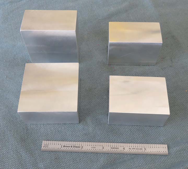
Bearings These aluminum blocks will be used with the shafts that
have keyways. What I'll be doing is boring a hole in the center for two
bearings each. I'll also be adding some 5/16-18 threads to
the blocks but I wanted to do the hard part first just in case I had a
problem.
|
|
|
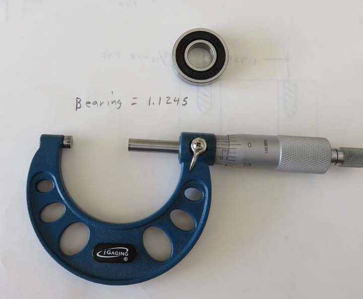
The first thing I need to know before machining anything
is the size of the bearings (this is what I should have done with the
press fit ball plungers). Anyways, the bearings measure 1.1245" so I'll
want my holes to be slightly under that. What I'll be shooting for is a
size of 1.1240" so I'll have a .0005" (half of a
thousandth) press fit. To give you an idea of the what .0005"
represents, it's one quarter of a human hair.
This won't be easy to do on my milling machine because
it's very old along with the style of boring head I'll be using. On the
other hand, I'll just take my time and do the best I can.
|
|
|
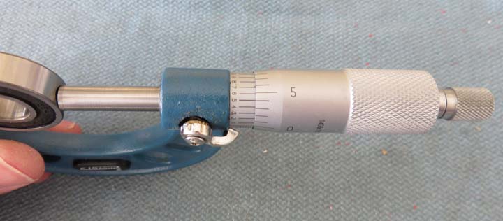
Here I'm measuring the bearing to show you what it looks
like when you have a reading that is between two whole numbers. Notice
the lines on the right side and how 'one' of them lines up with the left side.
The number 5 lines up perfectly which means it's exactly between two
whole numbers. And in my case the number is 1.1245. If one of the lines
were to line up with say the four on the left side, then my size would be 1.1244.
This is what you call a 'vernier scale', which is when you use graduated
lines to aid in taking your reading. Just things I deal with in the
industry.
|
|
|
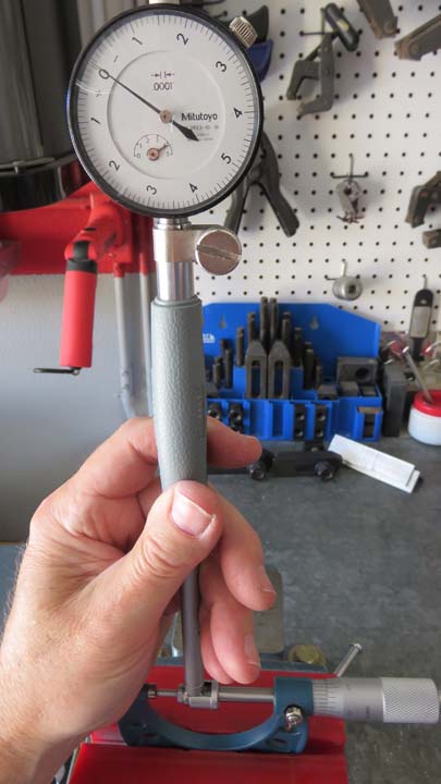
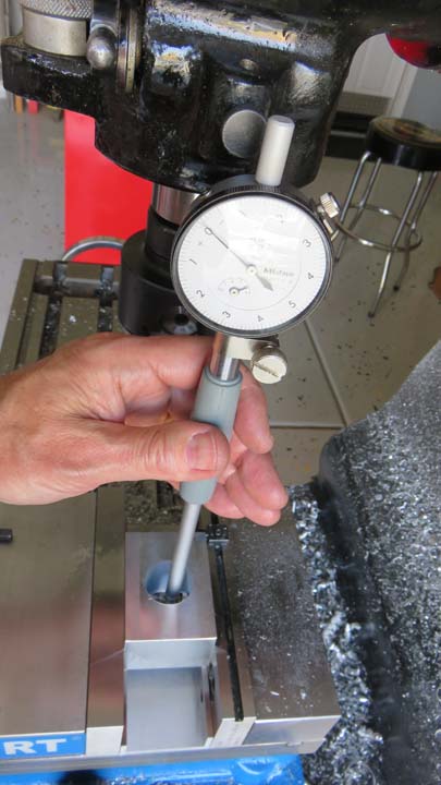
What you see here is a 'dial bore' gage that I borrowed
from my work. I'm using it to measure the inside diameter of the hole
I'll be boring. Setting the gage can be done a few different ways and
I'll be using the micrometer that I measured the bearing with. This is a
very accurate way of measuring a hole and is easy to use.
Although this micrometer isn't of the best quality, it will work great
because it's the same one I used to measure the bearing with. I placed
the micrometer in my vise using soft jaws, I then set the size that I
wanted (1.1240) and locked it in. Now these dial bore gages use
different length probes depending on the diameter that you're measuring.
Once I had everything in place, it's time to zero out the gage.
To set the gage to 'zero', I'll need to make sure it
reads the lowest point possible. To do this you move the gage
side-to-side and and then front-to-back, keeping the probe tips centered
on the micrometer until you get your lowest reading. Once I have this
lowest reading I
unlock the outer dial, turn it to zero, recheck it a couple of times and
then lock the dial again. Once it's locked I check it one more time and
if everything looks good, my gage is ready to go.
|
|
|
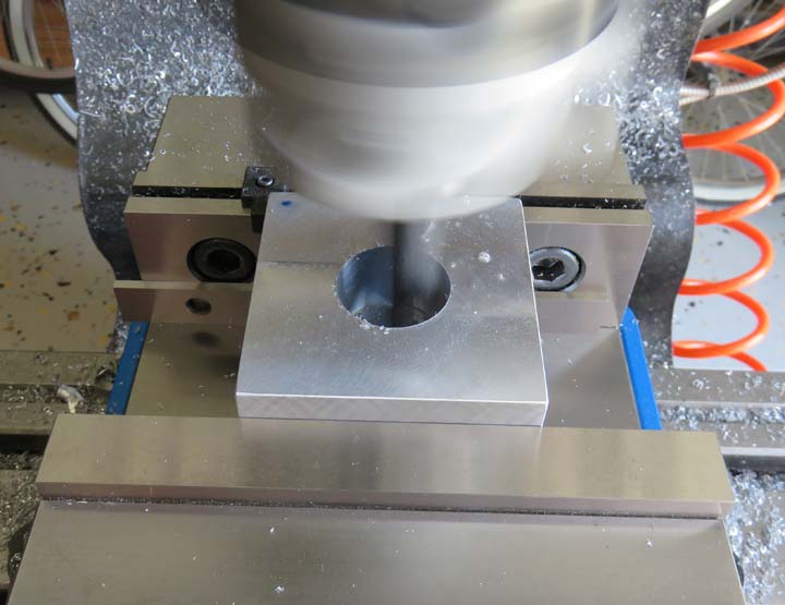
This is the larger of the two blocks here but all the
holes will be the same size. BTW, I'm making two of these larger blocks
even though I only need one just in case I mess one up. I roughed the
hole out with a 1/2" drill and then a one inch drill before starting the
boring process. In this shot I'm about half way through this cut with
the boring bar spinning.
Note the blue dote in the upper left corner of the
block. This is to make sure I put the block back in the mill vise the same
way every time. As I roughed the material out with my boring bar, I left about .010" in the
hole and then changed blocks and roughed the other one. Once both blocks
are the same size (undersize), I can then adjust the boring head until I
have the correct size and leave it there. This way it should repeat the
hole size for the other block (in theory).
|
|
|
This is a slow process because you have to take very
small cuts, check your progress and repeat as needed. In other words,
taking your time is a must here. In this shot you can see that I've hit
the dimension that I wanted (zero on the dial) so this is a good part.
|
|
|
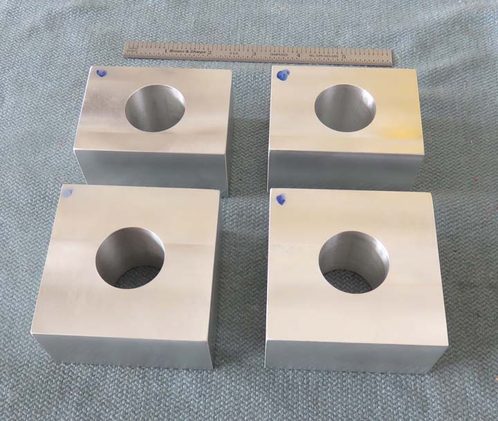
All of the holes came out to the right size so it was a good day.
Now would be a good time to explain what I'm doing exactly. Only a few
of the gears will need these bearings and the ones that do won't be
removable. And if you remember earlier I mentioned something about
chains, well some of these smaller blocks will have sprockets, gears and chains
but I'll get to that later.
|
|
|
Miter Gear Box
I've never worked with miter gears (or bevel gears) so
this will be a challenge. Don't get me wrong I understand the concept
behind them, I've just never had the pleasure of making anything out of them,
till now that is. Bevel gears transfer motion of two intersecting
shafts at a right angle. Miter gears are a special type of gear designed
to operate in pairs with identical numbers of teeth and diametral
pitches, along with a 1:1 ratio.
What I'll be doing is building a housing for the miter
gears to work inside of. This unit will take the motion from the all the
moving gears on the plywood and transfer it to the rear of it. Once it
transfers this motion to the back, it will then move a horizontal shaft
that will do something special, like dispense an item (more details
later).
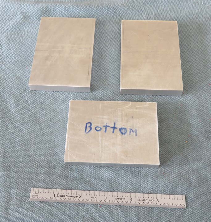
The sides and bottom will be made out of 1/2" thick aluminum.
|
|
|
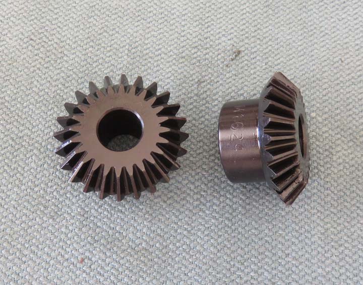
Here are the bevel or miter gears. These gears will be
90 degrees from one another along with the shafts that they ride on. The
hole size is 1/2" so they work with my shafts.
|
|
|
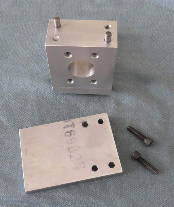
I'll need to bore some holes in the side plates for two
more bearings and I need to make sure they stay in alignment when I'm
finished. To make that happen I'll be using 'dowel pins' to line them up
with. Dowel pins work great for this and will ensure the two plates will
go back together in exactly the same place again-and-again. By using two
dowels and two screws these side plates won't move and they will be very
strong.
|
|
|
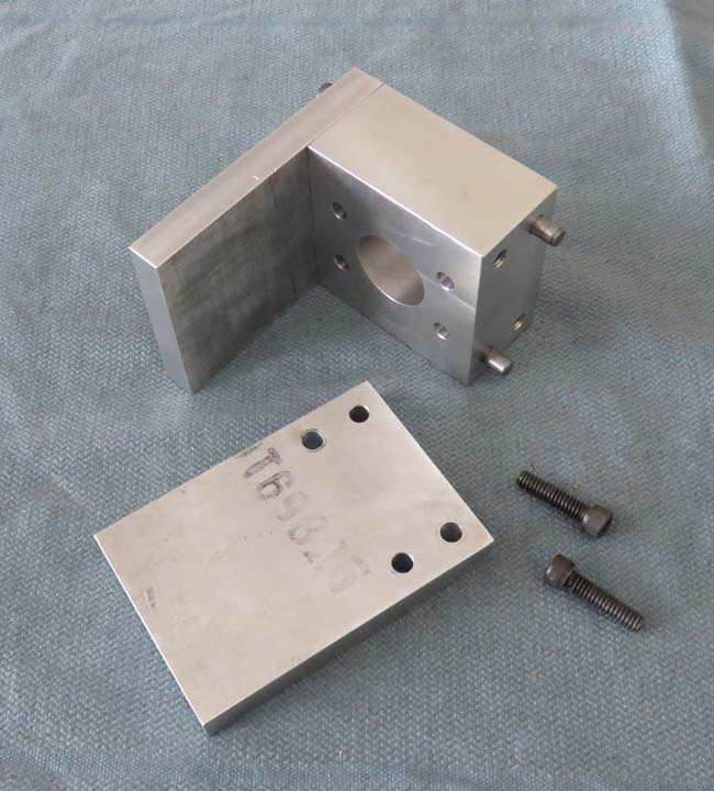
This should give you a better idea of what this will
look like once both sides are in place. The two bearing holes will be in
the center of the side plates side-to-side (short dimension) but off center top to bottom
(long dimension).
|
 |
|
1
2
3
4
5
6
7
8
9
10
11
12
13
14
15
16
17
18
19
20
21
22
23 |