33 Coupe Last Details 24
6/04/04
This is looking pretty good so far but
does it work? It sure does and it didn't cost me a dime....only some
time! The one thing that I might have to do is increase the ratio of the
pedal if it doesn't work as planned but that's easy too. I now have a
4.3:1 ratio and can increase it to 6.5:1 by drilling a new hole
3/4" from the existing one.
|
|
|
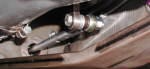
Here you can see what I'm talking
about a little better. By adding a new hole upward by 3/4", this
would increase my ratio to more of what it should be but I'll see how it
stops when I take it for a "real" test drive. I'll also need
to make a new spacer that goes between the brake pedal and push rod
bearing. I had to add four 3/8 washers and a longer bolt so the push-rod
would be on center because the existing spacer wasn't long enough. When
I tear down the car for paint, this will be on the list of things to do.
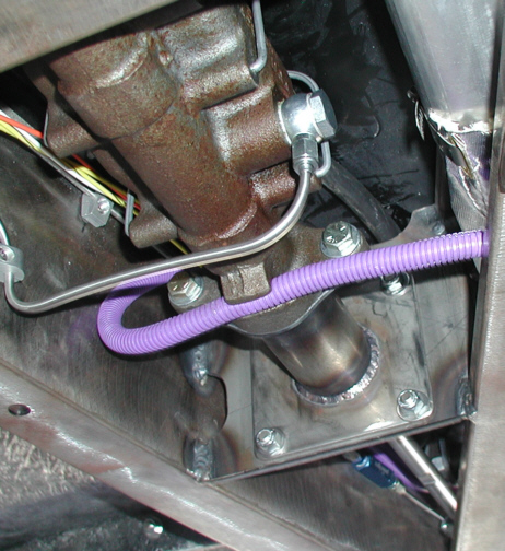
I now can remove the vacuum line that runs from the engine to the
underside of the car as it's no longer needed. Oh....and that driveway
test drive that I wanted to take earlier, that had to wait till the next
day, but was worth the wait. Let's just say, I know the posi-traction
unit works!!!
|
|
|
| 6/13/04
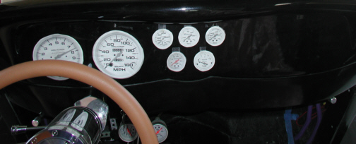
What I'm getting ready to do is install my
Autometer
gages
and if you've been following along, you might have seen this layout from
time-to-time in some other pictures. What you see below are some paper
cut-outs of some Autometer gages that I printed and then placed onto the
dash to give me an idea of what I wanted. By placing the cut-outs in
different locations, I finally decided on the pattern that I wanted. I
didn't want to install the gages till my seats arrived because I wanted
to be able to see all the gages while I was seated and do this procedure
only once.
|
|
|
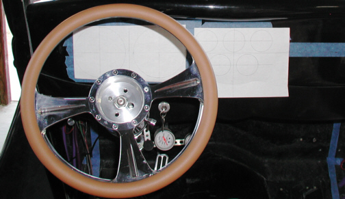
To layout the dash and make sure the
gages were centered, I first used some tape to go from one end to the
other and then I marked off some center lines. Now I needed two
different vertical centers for my layout, one for the larger gages and
one for the smaller ones. Then I used a compass to draw some circles on
a piece of paper to get the layout that I wanted. What I wanted was the
gages to have the same distance between them all, no matter where you
measured them at. Once I was happy with the results, I matched the center
lines on the paper with the centerlines on the tape. At this point, all
I needed to do was transfer the centers to the dash. I used a 1/16"
diameter drill in my electric drill motor for this task but didn't go
through the dash. What this did was give me seven small dimples in exactly
the location that I wanted. I then removed the paper and tape and
then used some dividers to draw my circles to the size needed.
Dividers have points on both ends which meant that one would go into the
small dimple that I just drilled and the other would scratch the surface
of my dash giving me a reference to go by. Let's break out the drills
and Dremel and get to work.
|
|
|
|
1 2
3 4
5 6
7 8
9 10
11 12
13 14
15 16
17 18
19 20
21
22
23 24
25 26
27 28 |
|
29 30 31
32 33
34 35 |
|