|
Main Rotor Nut 1
5-2023
|
I have a cool project that I'll be doing this time but
first a little history about the company that I use to work for and the
type of work we did when I worked their.
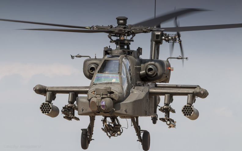
What you see below is the AH-64 Apache Helicopter made
for the ARMY by The Boeing Company. This helicopter has two pilots, is loaded with a modular armament system that can hold
different weapons, has a 30mm chain gun mounted to the underside
which is aimed and shot through a heads-up display like you're playing a
video game. This means that whatever the pilot is looking at, left,
right, up or down, the gun moves with his head to acquire the target. This
is truly the baddest rotary wing aircraft in our Military and the ARMY
is very proud of it.
So, you might be wondering, "what in the world are you
showing me this for"? Well, the aerospace company I use to work for, K.S.D. Inc; has made parts for this aircraft for the past 40 years. And
during that time I've personally made lots of different parts for this
gun
ship. And eventually programmed many of the parts for the CNC lathes and
milling machines, along with making tooling to run all these pieces
using a CAD/CAM system, over a span of 38 plus years while I was employed there.
|
|
 |
|
Some of the things that we made for the Apache were:
parts that went into the 30mm chain gun, a part for the cyclic stick
(which is a stick the pilot uses to fly the aircraft), main rotor nuts,
along with a few others. But most of the parts that were produced by K.S.D. Inc. were the tension torsion retention straps for the main and tail rotor
systems. These 'tension torsion retention straps' (or what we referred
to them as either big main's or big tails) connected the rotor blades to
the rotor mast, which were both 'critical flight safety parts'.
Eventually K.S.D. lost the contract with the ARMY for
the main rotor strap assemblies, but still produces the tail rotor
strap packs for The Boeing Company, which continues to this day.
|
|
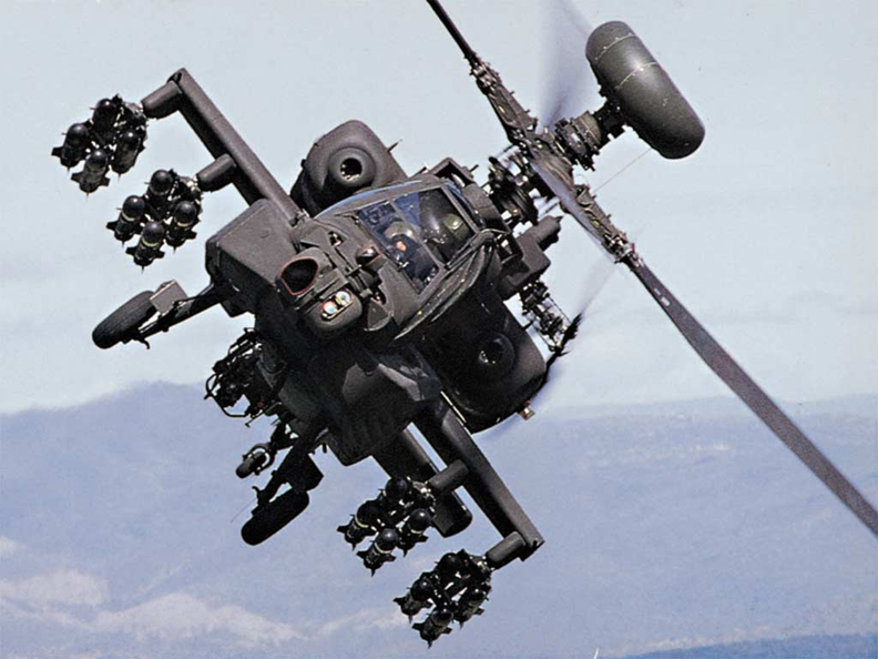 |
Helicopters should not be able to do this but as you can clearly see,
the Apache can do a roll.
|

|
|
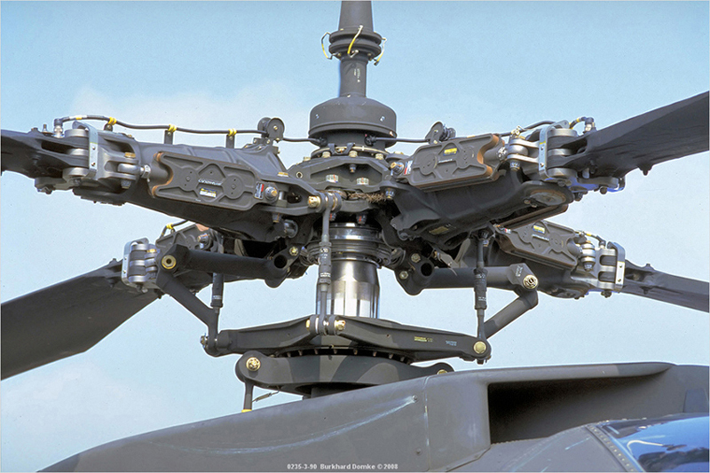
Anyways, this is the rotor mast, which has four blades
mounted to it. What you can't see are the main rotor strap packs I was talking
about that connect the blade to the rotor hub. Those strap packs are
inside and protected by a pitch housing (gray in color) to keep as much
dirt and foreign matter out of this area as possible.
|
|
 |
|
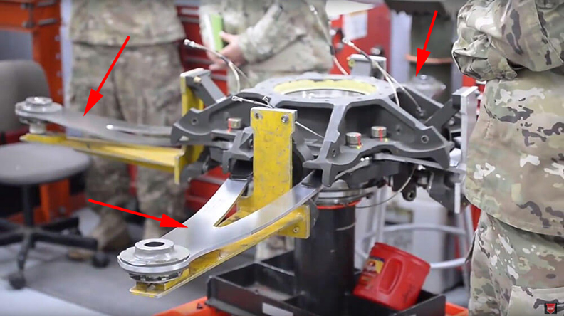
Here you can see the strap packs mounted to the rotor
hub (arrows) that are comprised of 22 laminates, which are .014"
thick each, along with a bunch of other components that are hard to see. K.S.D. made thousands of these strap pack assemblies without any
failures over the life of each contract they worked on. That's a good thing because if
just one of these strap assemblies failed, the entire rotor mast comes
apart and that's it for the aircraft and the pilots.
|
|
 |
|
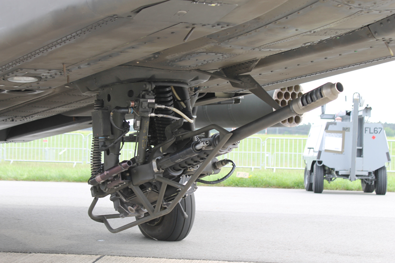
Here is the 30 mm chain gun mounted underneath. Just in
case you're wondering how big 30mm is, it's 1 3/16" diameter, which is
huge. The technical name for this gun is the "M230 cannon"
which can hold 1200
rounds of ammo, can fire 625 rounds per minute and is powered by
an electric motor.
|
|
 |
|
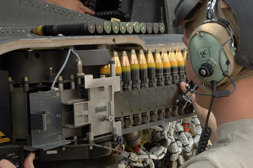
Here is some of the ammunition the gun shoots. Note: the High
Explosive rounds provide armor piercing capabilities with lethal
penetration.
* M788 Target Practice (TP)
* M789 High Explosive Dual Purpose (HEDP)
* M799 High Explosive Incendiary (HEI)
|
|
 |
|
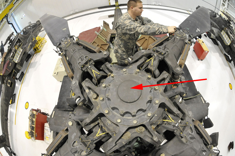
Main Rotor Nut
Here's a good look at the top of the rotor mast. Under
that cover the arrow is pointing to is where the "main rotor retaining
nut" is located, which holds the main rotor to the mast, and is what this
project is based on. I mentioned earlier that my work made some of these
nuts, which was in the early 2000's and I personally programmed and
turned many of them on a CNC lathe. And these nuts had a dozen 3/8-24
threaded holes that were machined in them as well.
Speaking of threads, these parts also had a single large
inside diameter thread, which my work had to subcontract out to another
company because it called for some special machining that K.S.D. wasn't
approved to do. Now this is common in the aerospace industry and is one
reason parts for aircraft are so expensive.
|
|
 |
|
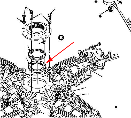
This schematic has a breakdown of parts that go into the
rotor hub. And the arrow is pointing at the main rotor nut that I'll be
using for this project. This nut along with the other components are
referred to as "critical flight safety parts". In fact,
this nut is known in the in Military and in the machining industry as
'The Jesus Nut'. The reason it's called The Jesus Nut is because if it
fails, you're going to meet Him. Almost all helicopters have a nut
similar to this one and they all have this same name attached to them.
Also in this schematic you can see the many smaller
threads in the main rotor nut that are part of the retaining or lock-up system for
the parts above it.
|
|
 |
|
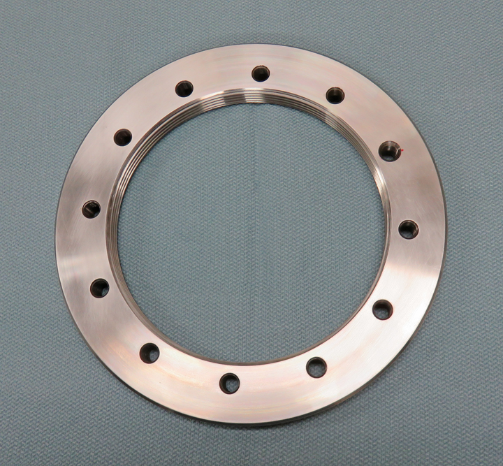
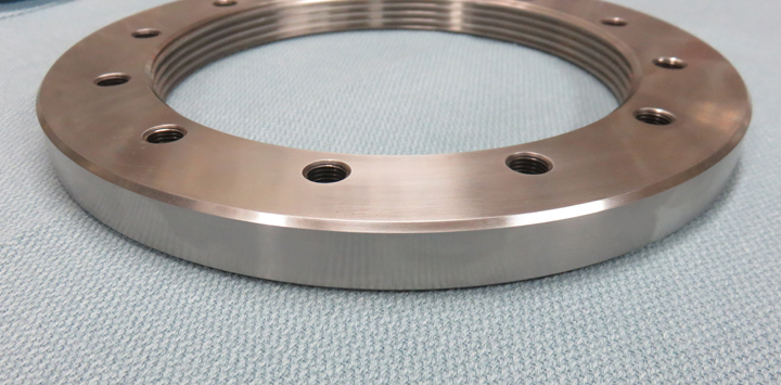
And finally the actual main rotor nut below that my work
made which I've been talking about. But before I tell you what this
project will be I'd like to tell you a little more about the life in a
machine shop and the machining process' that we go through.
Every machine shop has scrap parts and my work was no
different. Obviously the goal is to make 100% good parts every time, but
that's not a reality because of the many variables involved in
machining. A cutting tool might break, or a tap might wear out, or you
input the wrong offset into the machine and it cuts the part undersize,
or there was a small chip from the previous machined part that you
didn't notice and it got under your next work piece while it was being
machined, rendering the part out of blue print specifications when you
were done. There are many more ways to mess up a work piece in the
machine shop, and these are just a few of them, but you get the idea.
|
|
 |
|
The material for these main rotor nuts are unique and
expensive and is called Maraging steel. Here is an explanation of this
special kind of material:
Maraging steels (a portmanteau of "martensitic" and
"aging") are steels that are known for possessing superior strength and
toughness without losing ductility. Aging refers to the extended
heat-treatment process. These steels are a special class of
very-low-carbon ultra-high-strength steels that derive their strength
not from carbon, but from precipitation of intermetallic compounds. The
principal alloying element is 15 to 25 wt% nickel. Secondary elements,
which include cobalt, molybdenum and titanium, are added to produce
intermetallic precipitates. Original development was carried out on 20
and 25 wt% Ni steels to which small additions of aluminum, titanium, and
niobium were made; a rise in the price of cobalt in the late 1970s led
to the development of cobalt-free maraging steels.
This material gets heat treated to a state of being very
tough, around 44 Rc. And with this hardness it's still very machinable
after being heat treated, which is what we did to bring in the final
dimensions. Now this toughness is ideal for this application because you
don't want the material too soft where it would bend, or to be too
brittle either where it could break.
Engineers that design parts like this have to walk
a fine line because of the critical nature of where a part is being used,
the stresses that it will see, along with how much the part weighs when
it's finished. It's easy to over engineer a part, which makes it
stronger...yes, but when you do that it becomes heavier as well.
Anything that is going into an aircraft needs to be as light as
possible, but strong at the same time.
Those smaller 3/8-24 threads are tapped using a rigid tap
in a CNC milling machine. These threaded holes are then checked with a
go/no-go thread gage to make sure the threads meet specifications as
you're machining them. And as I mentioned before, things can happen. But
if a problem does occur, for any reason at all, and you find the part
has a wrong dimension or something else that doesn't meet blueprint
specs, it's 'Red Tagged' (rejected) which is then put in a special bin
and placed aside.
We had a few of these parts that ended up not meeting print for
one reason or another (flatness, bad thread, surface finish, dimensional
tolerance, etc;) and once they were set aside, I had an idea what I
could use them for. So what am I going to make this time?
|
|
 |
|
Well, this part is approximately 8 1/4" outside diameter,
with a 5 3/4" inside diameter by 5/8" thick, along with the 12 holes,
that I think will make a great looking 'clock'. So there you have it, I'll
be making two clocks this time which should be a really fun project with
a great back story.
|
|
1
2
3
4
5 |
|