Lathe  2                                              09-2020


Accessories


Most machines like lathes and milling machines (these days) have DRO's or Digital Read Outs. However, they cost a lot more and when I bought my lathe, I decided not to get one. What I'll use in place of a DRO is this one inch travel dial indicator. Now this is no-way comparable to the other, but it's good enough for most of the work I'll be doing. Now I need a way to clamp this indicator to my lathe.


I made this bracket out of aluminum to hold my indicator. The bottom piece is made out of steel because it will slide along the bottom of the steel ways of the machine and I didn't want it to wear out.


The longer screw will go through the bracket and thread into the steel piece. This will enable me to tighten or loosen the bracket by hand so I can position it where I want it. The smaller thumbscrew will hold the indicator.


This setup works great and it's easy to adjust left or right depending on what I'm working on. And it's easy to remove the indicator as well. The way it works is when it's clamped to the machine, the indicator tip moves when the carriage pushes against it. Now I've also used different length blocks between the indicator and carriage to give me more indicating capacity if I need it. It's not a perfect system but it gets me by.


Here are some of the tool holders I bought. The piece on the left is what all the other holders clamp to, called a quick change tool holder. That handle threads into it and depending on which way you move it, it will tighten or loosen the holders.


I bought some steel angle from the hardware store to help hold all my tool holders. The piece was six feet long and is 1" X 1".


These are just over 1/16 thick steel, bent to 90 degrees with a 1/4" hole for a bolt. I made them to hold all my tool holders and I plan on bolting them to the steel angle.


I screwed the long steel angle to the backsplash, fastened the pieces I made to the steel angle and slid the tool holders over them. Now all my tools are close by.


Working With a Lathe


Before I talk about how the lathe works or functions, just know there are a lot of knobs and levers that makeup this machine.

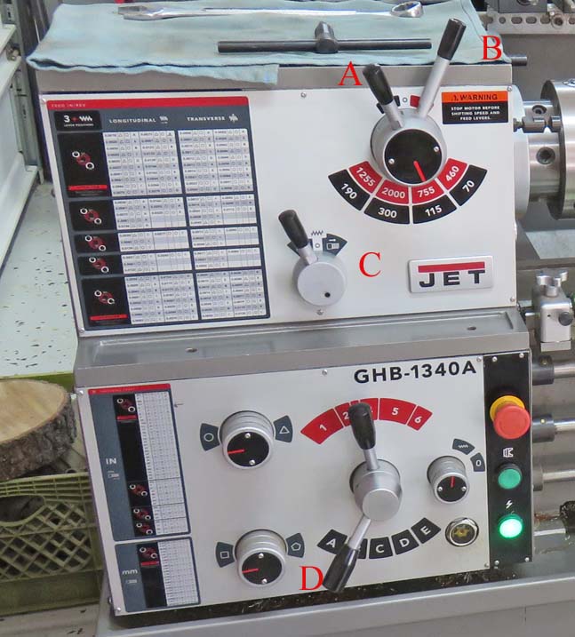
Here is the central nervous system of the machine. First I'll talk about the two levers at the top right: the rear lever, B, is for low range (black) or high range (red). The lever in front of that one, A, is where you select the rpm, which changes depending if you're in high or low range. Now the spindle must not be turning while moving either one of these levers because this is not a synchromesh transmission.

The small lever below and slightly to the left, C, is for feed direction... when the feed is engaged. 
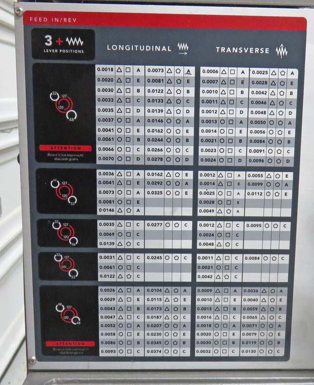
And again, you only move this lever when the spindle is stopped.

The charts to the left is for all the different feed rates, which I'll show you in more detail in the next picture. Also notice there is a chart on the top section and bottom section. The top is for normal feed rates and the bottom has all your threading information. More details to follow.

On the second level is where you turn two different knobs and move one lever to change feed rates. The top chart has many different feed rates and once you've selected the one you want, that same row has some different shapes or icons that correspond to the knobs and lever positions in the chart (top). If you look close you can see one knob is pointing to a 'circle' and the other is pointing to a 'square'. And lever, D, is in the B position. This feed rate equates to .0061 feet per minute. This system works, but it takes time to get use to it.

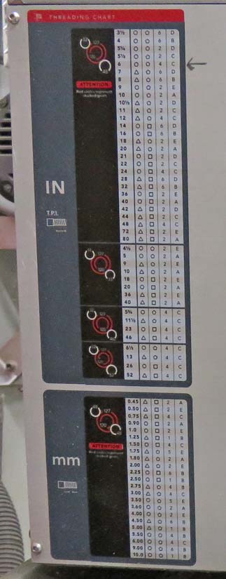
For threading there is one more lever to deal with, and that's the one above lever D, (with all red numbers). Notice that lever is in the number 3 position. This is a type of neutral position (when you are 'not' threading) which is where it stays most of the time. I'll show you the threading chart in more detail at the bottom of this page.

The BIG red button is the E stop, or emergency stop. Hit that and everything stops.


Here is a close-up of the top chart. Longitudinal moves the carriage left or right and Transverse is for the cross slide which is for feeding in and out.

The pictures with the white and red circles represent gears that you can change on the side of the machine depending on the feed rate that you need or want. Now this is a pain to change on a regular basis so if you can get away with using the feed rates in the top section then life is that much easier.


This chart is on the second level and is for threading. Notice I have an arrow pointing to a row that I've used on a previous project. The first number in that row is thread pitch, or number of threads per inch. Depending on the thread pitch that's needed this is where you would start. And In my case it was six. Next you would put the two knobs in their correct positions according to the chart. And last you would need to move two levers into their corresponding positions.

However, if you wanted a certain thread pitch that wasn't in the first section, then you would have to change some gears like I talked about earlier. The hardest part about changing these gears is getting the backlash just right. So how do you know when the backlash is correct? When there is almost no noise coming from these gears. But, If it's off just a small amount, you'll know by the whine or sloppy sound coming from that area.


1    2    3    4