|
Working With Metal Continued
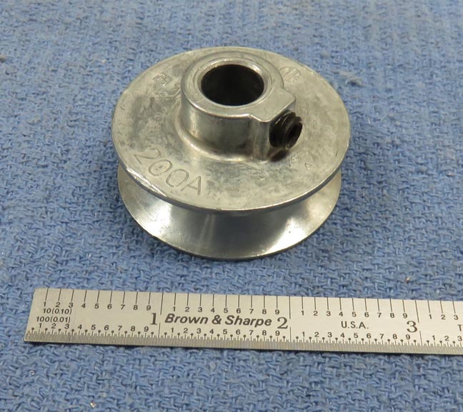
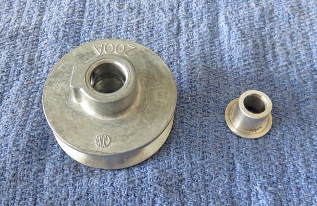
Here is the store bought pulley that my son-in-law gave me, which
will be used on the motor. It's 2" in
diameter with a 1/2" hole.
|
|
 |
|
I mentioned earlier that the motor has two rpm's, which
are 80 and
50. But both of these speeds are still too fast, so I'll need to slow it down.
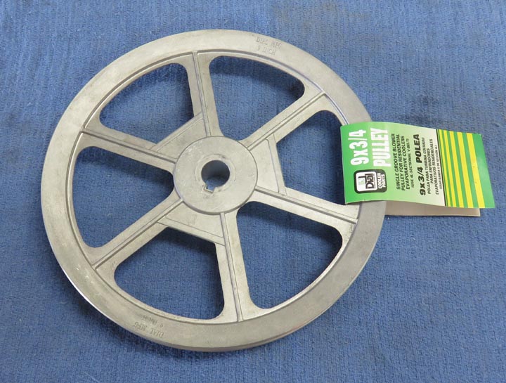
And to do that, I'll be using this 11" pulley at the other end where the
arm is at. This will give me 4.5:1 reduction which should be just about
right.
|
|
 |
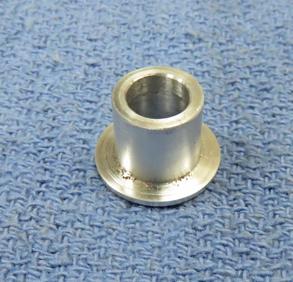
This is the adapter I made for the smaller pulley, which is made out of
aluminum. The flange on this adapter is 3/4" diameter, the smaller outside diameter is
1/2", which will go inside the pulley.
|
|
 |
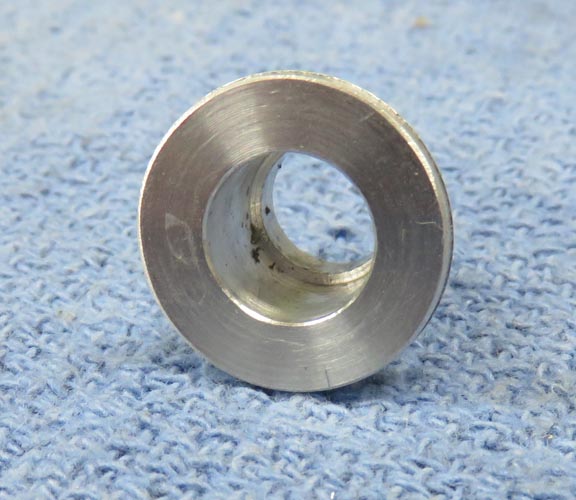
I machined two diameters on the inside that will mate up with the motor
shaft. And I'm sorry the inside diameter is so dirty because I forgot to
clean it before taking the picture.
|
|
 |
I will be using the adapter from the top side of this pulley.
|
|
 |
|
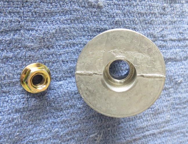
Here is the metric nut that came with the motor. In
order to use it I had to bore out the back of the pulley to accept it.
And I made sure to make the bore large enough to use a socket on
so I could tighten
it.
|
|
 |
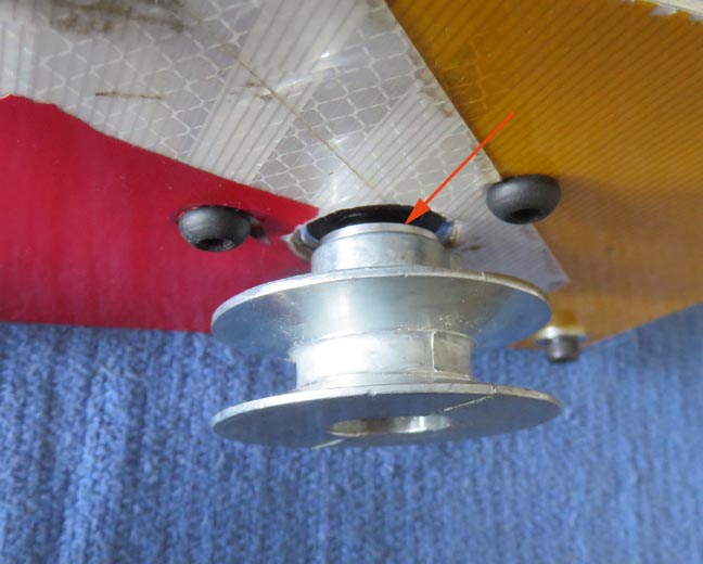
The arrow is pointing to the adapter which worked out great. And you can
see the other side of the aluminum road sign.
|
|
 |
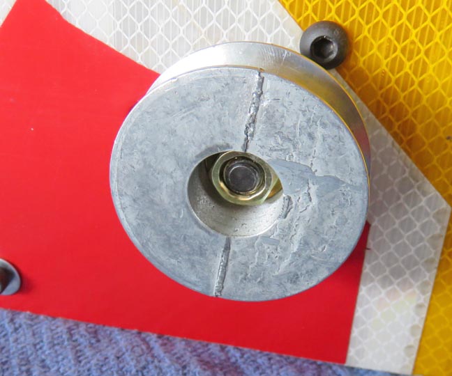
With the nut nice and tight, this part of the assembly is finished. Now
it's time to work on some other parts.
|
|
 |
|
Now it's time to work on the opposite end where the larger
pulley will go. The
moveable arm will be on this end and it will extend vertically three
feet high. Also, another two foot arm will be fastened to this vertical arm and
extend out another two feet horizontally. This arm will be made out of
1" X 1" X 1/8" wall steel angle iron. This also means it
will become a large lever, so everything below this arm will have to be built very
solid.
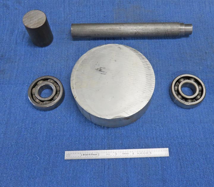
The pieces below are what I'll be using to support this
arm assembly. The piece at the top left is what the arm will be welded
to, which is 1 1/4" diameter steel and will bolt to the shaft. I'll call this
piece "the adapter'.
The piece to the right of that will become the
pulley shaft, which is 1" diameter steel, and those two bearing will get
pressed onto this shaft. Last is the bearing housing (in the middle) which is 5"
diameter and made out of aluminum.
|
|
 |
|
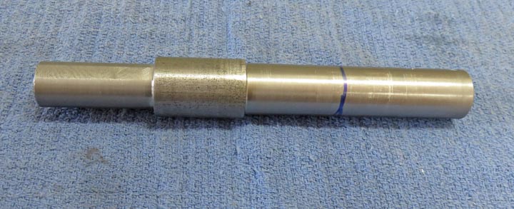
I turned the left part of this shaft down to 3/4" which
is for the pulley. The other end will have the bearings pressed on it and will go through the wood floor.
And this end will have the adapter
bolted to it, which is why this end is so long.
|
|
 |
|
1
2
3
4
5 |