33 Coupe Steering Column 6
11/3/03
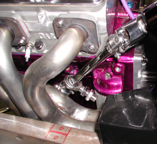
This is what it looks like now that
the two lengths are in place. The next thing that has to be done is to
make a steering shaft support. The rule is if you have more than two
U-joints, you have to use a support. If you have more than three
U-joints, add another support. I'll be making my supports because I have
no idea where I could buy one.
|
|
|
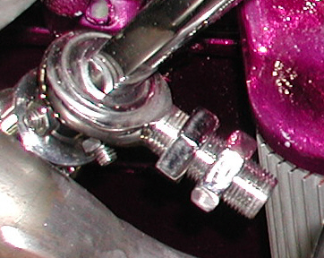
This is the support that will be used
which is also made by Borgeson. The thread size is 3/4-16 and the two
nuts are used to fasten it to a bracket. Lets take a look at what the
bracket will look like.
|
|
|
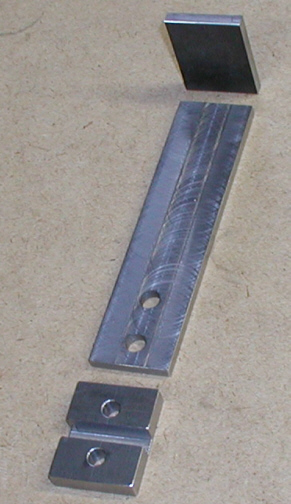
Here is the bracket in it's rough
form. I'll be Welding the piece on the bottom to the frame rail and the
longer piece will get bolted to it. Now the piece that is getting welded
to the frame doesn't have threads in it yet. The reason for this is
because this piece is 3/8" thick and the size of bolt is going to
be 3/8-16 but I want all the strength I can get and not have this
sticking in the air to far (don't want it to be to ugly). What I plan to
do is after I weld the piece on, I'll then drill through the frame using
these two holes as a guide. That way when I tap the threads, I can also
use the thickness of the frame (1/8") as part of the threads for
all this. Now to give you a little history on the strength of fasteners,
say like a bolt, the bolt is only as strong as it's cross section plus
one thread. Now I have a 3/8 diameter bolt and the thickness of my block
is the same. This is where the extra thickness of the frame comes in to
add to the strength of the threads. See how all this comes together!!
Now if you were wondering what the slot is for in this block, just
remember how close the brake line is to the headers.
|
|
|
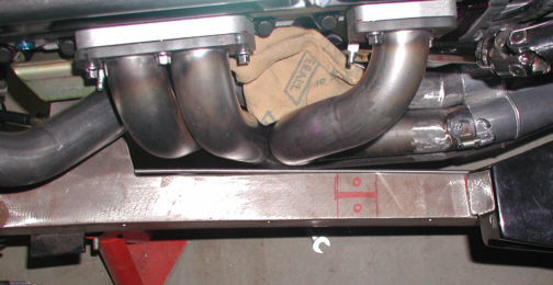
Here is a better shot of how close the
brake line is to those tubes. I'll be re-routing it to the top of the
frame rail to get it away from the heat. Notice the red out-line of
where the 3/8" thick block will be welded. Now picture the brake
line running through the center of it. I made the slot width and depth
the same which is clearance enough for the brake line and some rubber to
protect it. I plan to run the line up the frame about four inches to the
right of the body that you see in the picture below. Then I'll make a
slot in the end of the body that rides on the top frame rail, continue
along to the top through the block to the other side of the number one
cylinder and then back down the frame to where it originally fastened.
With the inner fenders installed, it won't be very noticeable. I thought
about running it on the outside of the frame but I think this work
fine so here we go.
|
|
|
|
1 2
3 4
5 6
7 8
9 |
|