|
This is the opposite end and this had 7/16-20 threads in
it. I won't be able to use them for this project but I did have to use
an extra long center drill to reach the bottom of the hole. Notice the longer one
next to a standard length one to the right. Once I was all finished drilling, the
mismatch in the middle was minimal so this worked out
great. All this so a wire will pass through it.
|
|
 |
|
Drilling and Tapping
Now it's time to start thinking about attaching things,
like a base to have it sit on along with some lamp hardware. And being
that this cam is pretty soft, I can drill and tap some holes without any
problems. Speaking of holes, the two that you see on either side of
center were in the cam when I bought it. As luck would have it, they
were exactly the right size for 3/8-24 threads.
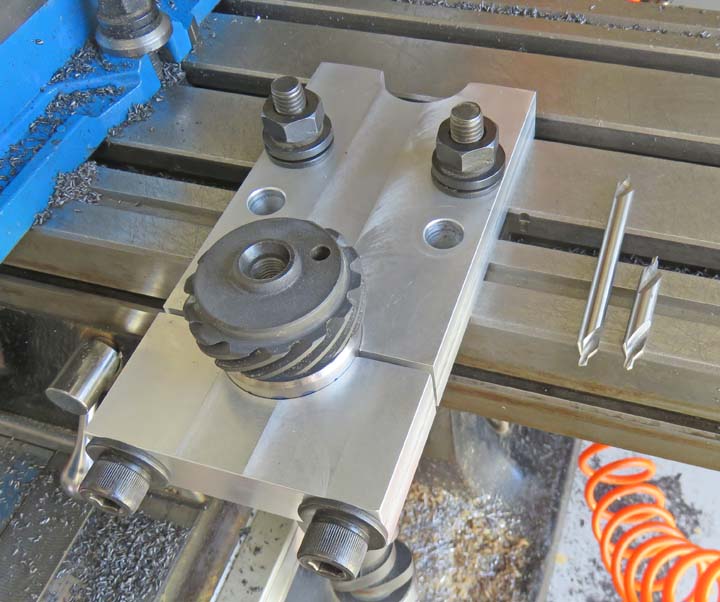
What I decided to do was drill and tap this thread size
in four places, not just the two that you see below. But to use these existing holes I
would need to know what 'bolt circle' or radius they were on. Once I
figured that out I used my indicator to find center, then using my
indicator again, I aligned the two existing holes so they were parallel
to the Y axis. Once everything was in
alignment I drilled the other two holes and then I tapped them all with some
3/8 fine threads. I decided to use this end for the top but with these
holes being so close together, I don't think I can use hex bolts because the
heads will touch each other. Don't worry, I have a plan.
|
|
 |
|
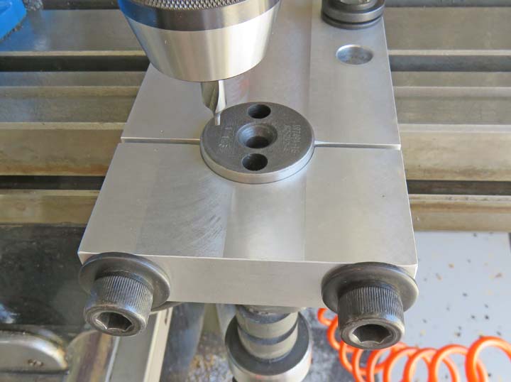
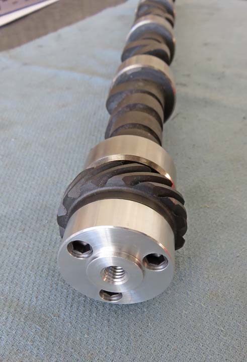
The opposite end will be used for the bottom or base.
And as you can see I've drilled and tapped three 5/16-18 holes. I split
the difference between the outer diameter and the spud in the center for
these new holes. The smaller hole at 12 o'clock had the dowel
pin in it and I won't be using it.
|
|
 |
|
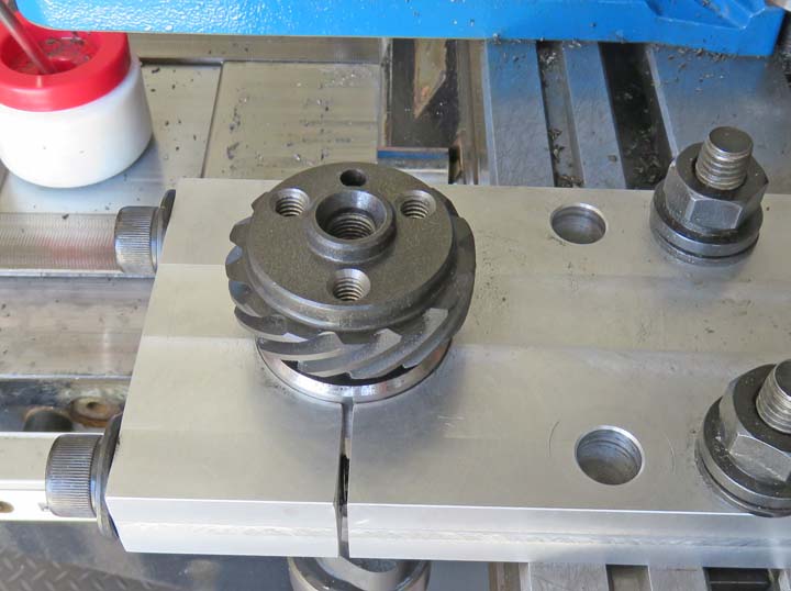
I started thinking about how I was going to make my
adapter for this end and decided to make it easy on myself so I removed
the boss (spud) completely (see the picture above if you don't remember). While I was getting close
to the bottom surface I started taking lighter cuts, only to find that this
end wasn't square with the surface that I'm holding on (cam journal). Notice the
plating that didn't clean up on the left side. This is how I knew this surface
wasn't square with the remainder of the cam. No I didn't
leave it like this, I took this picture before I made another cut so the
entire surface was cleaned up.
|
|
 |
|
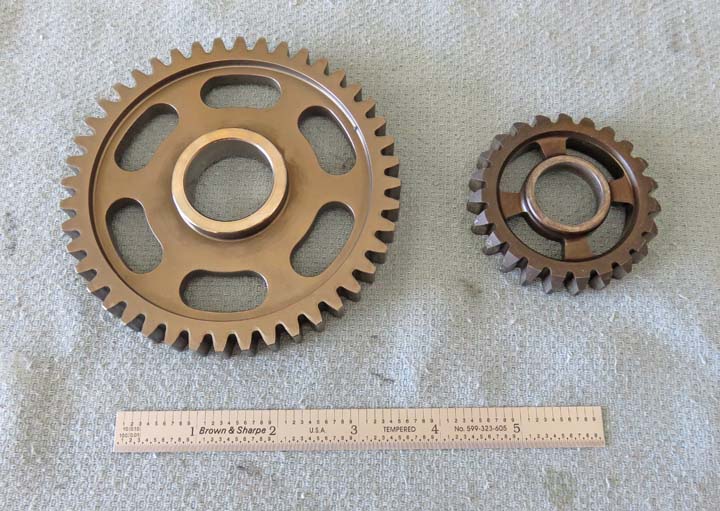
The Base & Adapters
Here are some gears that I'll be using for this project.
Speaking of gears, my daughter Tracey, brought over a bunch of gears
awhile back to be used for another project. However, I only used 'one'
gear up to this point, and that was for her lamp project.
I went through all the remaining gears and this was the
biggest one I could find, which will be used as the base. It's about 4"
in diameter and should fine for what I'm making. The smaller one will be
used as eye candy. In other words, the smaller one won't be functional,
it's just to look cool.
|
|
 |
|
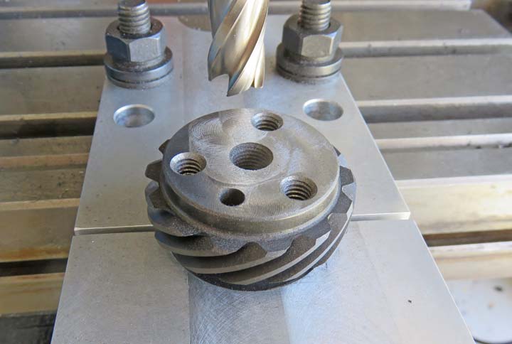
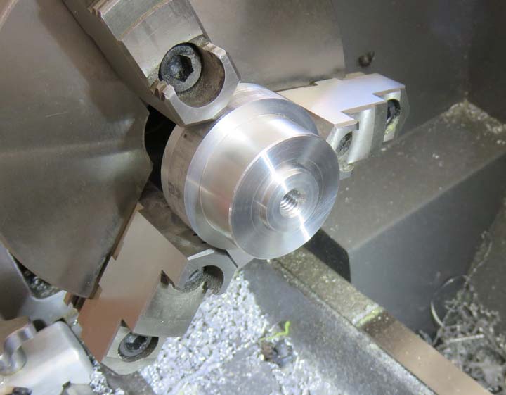
I'm making all the adapters out of aluminum and this one
will be used at the bottom. That spud is sticking out .100" and will locate the
smaller gear, which I'll show you in a minute. The thread in the center
is 3/8-16 and will be used to hold the base together (large gear).
|
|
 |
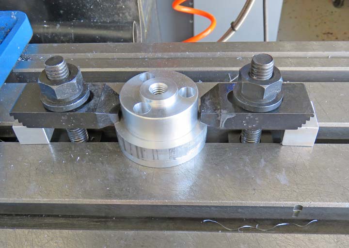
I left the shoulder on the adapter for now and I'm using it for a
clamping surface. What I did was drill and counterbore some holes for
the 5/16" screws but didn't go all the way through.
|
|
 |
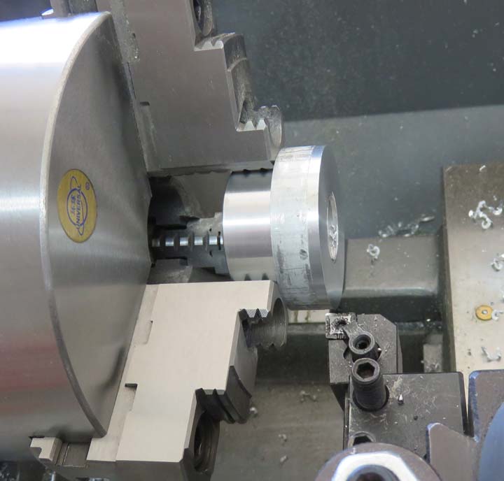
Now that I have all the holes drilled and a thread in the center, I'm
ready to face off the excess material. This went quick and it was very
easy.
|
|
 |
|
Notice
the screw heads have been turned down. This was necessary because of
clearance issues between the spud and outer diameter of the adapter. All
I did was put the screws in my lathe and took a few cuts till I had what
I wanted.
|
|
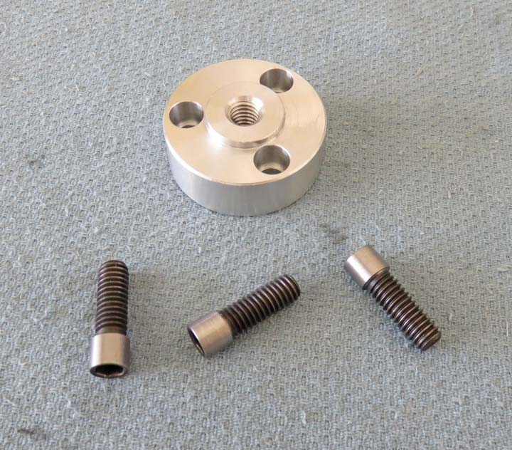 |
And there you have it, one adapter is finished and bolted up. This worked out great and
now I'm ready to make another adapter.
|
|
 |
|
1
2
3
4
5
6 |