|
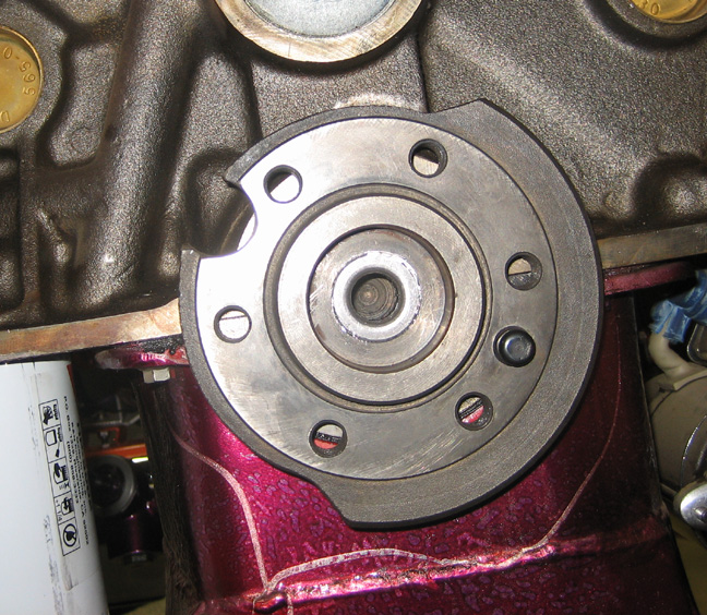
This didn't work as well as I'd liked it to but it did
press in. As you can see a lot of the shim didn't get pressed inside
hole but some of it did
it's job. I could tell as I was hammering it in that it did have a press
fit so that's a good thing.
|
|
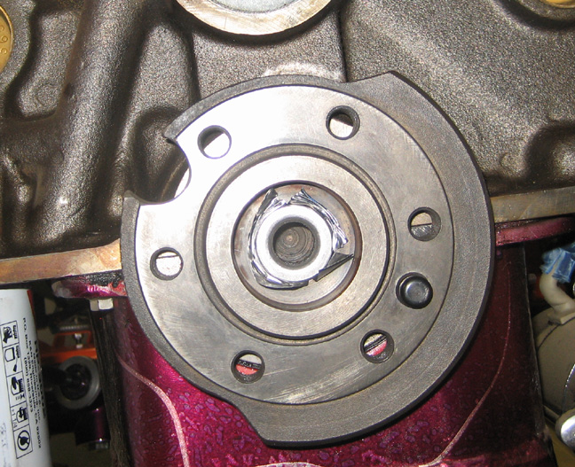 |
After removing all the remaining shim stock with a
triangle burr knife, this is what it looks
like. Now the good news is that this area is recessed so if any shim
stock is sticking out it won't make any difference. I do know the
bearing won't go any deeper because of the ring I made and it shouldn't
come out either as the input shaft on the trans will keep it from
falling out. If this doesn't last
and starts to make noise, I'll have to make one
and be done with it. Wish me luck!
|
|
 |
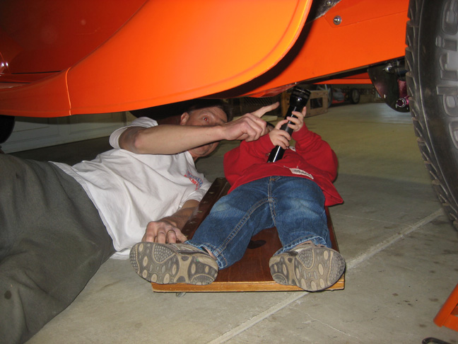
My grandson, Aidan, came over for the night and wanted to see what I was
working on. He's three years old and loves to explore in the garage. It
was nice taking a break so I could see him because he's at that age
where he wants to learn. Here
you can see him telling me how to install my new clutch which I was just
getting out of the box when he arrived. But first I'll need to reinstall
my flywheel again :-[
|
|
 |
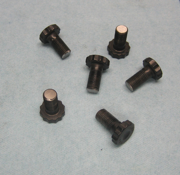
The first time I had the flywheel installed I noticed that the bolts
were sticking out of the back a little and were really close to my rear
main seal. I didn't want to remove it when I first saw it but I have
been wondering about them ever since. While the flywheel was off I took
this opportunity to shorten them by about .100" on my belt sander. I
guess I could say removing the flywheel and reinstalling it had a silver
lining after all.
|
|
 |
|
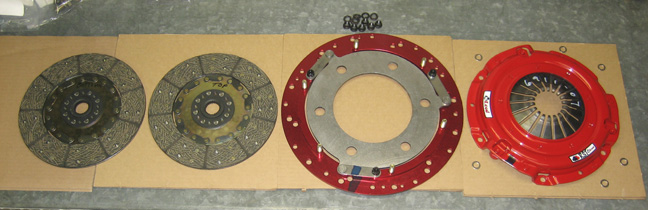
Here is my twin disc RST clutch by McLeod. From left to right are the
bottom and top clutch discs, floater plate and pressure plate. One disc
goes on either side of the floater plate once everything's installed and
it makes a difference which disc goes where. If you look close you can
see the word 'top' on second disc and the other is labeled 'bottom' but
it's hard to see. Just to make sure they get installed correctly they
both have a sticker on the back side that says 'flywheel side' so you
don't get in trouble. The way this goes together is from bottom to top
with the bottom disc starting at the flywheel. After that the floater
plate goes on and then the top disc. The pressure plate bolts on last
which completes the sandwich. The quality looks to be very nice and
I'm pleased with it. This twin disc setup is good up to 800 hp but it
has a nice soft pedal feel so you don't wear your leg out either. How is
this possible because back in the day this was unheard of? Well I
wondered that myself and this is how I understand it.
By using a pressure plate that uses mild spring pressure to engage
it, you wouldn't normally be able to give it much horsepower without it
slipping. But if you were to add some surface area into the mix then you
could. This is were the two discs come in because it adds more total
surface area. Now this twin disc setup doesn't use a normal size clutch
disc like a 10 1/2" or 11" but instead uses two 9 1/4" pieces. One
reason for this is to help keep down rotational weight because using two
larger discs would be much harder to spin. The discs are made out of
organic materials which provide smooth engagement along with a soft
pedal.
|
|
 |
|
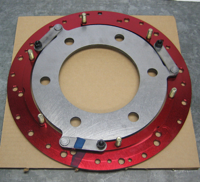
Notice the dark looking mark at the six-o-clock position, that lines up
with the same dark mark on the pressure plate. This is a way of making
sure you re-assembly it the way it was intended which is a good idea.
The floater plate is made from a solid piece of aluminum which is red
anodized and comes with three different alignment tools (depending on
what engine you're installing it in).
There is one thing that's a little confusing which is the amount of
bolt holes around the perimeter. There are three different sizes here,
two sets of 3/8" (six each), some 5/16" and a few 1/4" but I don't
know what they're all for. My flywheel has two sets of 3/8" holes in it
but each set has a different bolt circle but I do know that I need six
3/8" holes to bolt the thing up. To throw a wrench into the works (no
pun intended) when I get six of the 3/8" holes to line up, the second
set of 3/8" holes line up too. After looking at the picture that came
with it I choose the outer set of holes. And once the pressure plate is
bolted on, this other set of holes (inner) would be much harder to get
to. It's a very nice setup and I hope it works as good as it looks.
|
|
 |
|
1
2
3
4
5
6
7
8
9
10
11
12
13
14
15
16
17
18
19
20
21
22
23
24
25
26
27
28
|
|
29
30
31
32
33
34
35
36
37
38
39
40
41
42
43
44
45
46
47
48
49
50
51
52
53 |
|
54
55
56
57
58
59
60
61
62
63 |